


68 Chapter 5—Digital I/O & Cascading
DM2000 Version 2—Owner’s Manual
Terminating External Wordclocks
Wo rdclock signals distributed via BNC cables must be terminated correctly, otherwise, jitter
and synchronization errors may result. Ideally, you should make a separate wordclock con-
nection to each device and terminate it. The following examples show two ways in which
wordclock signals can be distributed and how termination should be applied in each case.
Normally the WORD CLOCK 75Ω ON/OFF switch should be set to ON. The OFF setting
provides support for wordclock source devices with special specifications.
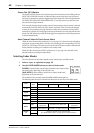
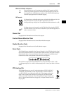
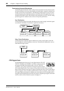
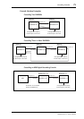
Star Distribution
In this example a dedicated wordclock distribution box is used to supply wordclock signals
to each device individually. Termination is applied at each device.
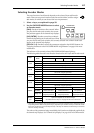
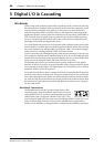
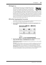
Daisy Chain Distribution
In this example the wordclock signal is distributed in a “daisy-chain” fashion, with each
device feeding the wordclock signal on to the next. This method of distribution is not rec-
ommended for larger systems.
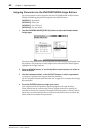
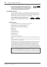
2TR Digital Outs
The DM2000 features three sets of 2-track digital outputs: 2TR OUT
DIGITAL AES/EBU 1 and AES/EBU 2 use XLR-3-32-type connectors
and output AES/EBU format digital audio. 2TR OUT DIGITAL
COAXIAL 3 uses a phono connector and outputs consumer format
(IEC-60958) digital audio. These outputs can be patched to the Bus Outs, Aux Sends,
Matrix Sends, the Stereo Out, Input or Output Channel Insert Outs, or the Control Room
signal (see page 81). They can also be patched to Direct Outs (see page 81). These outputs
can output digital audio signals at sampling rates other than the current DM2000 rate by
using the internal sampling rate converters (see page 69). Digital output signals can be dith-
ered for transfer to lower-resolution systems (see page 73).
WC OUT
(BNC)
WC IN (BNC) WC IN (BNC) WC IN (BNC) WC IN (BNC)
Wordclock
master
Wordclock
distribution box
Device-A
Ter mination = ON
Wordclock slave
Device-B
Ter mination = ON
Wordclock slave
Device-C
Ter mination = ON
Wordclock slave
Device-D
Ter mination = ON
Wordclock slave
WC IN
(BNC)
WC OUT
(BNC)
WC OUT (BNC)
WC IN
(BNC)
WC IN
(BNC)
WC OUT
(BNC)
Device-A
Ter mination = ON
Wordclock slave
Device-B
Ter mination = ON
Wordclock slave
Device-C
Ter mination = ON
Wordclock slave
Wordclock
master