


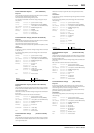

MB2000 Peak Meter Bridge 387
DM2000 Version 2—Owner’s Manual
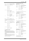
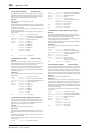
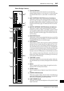
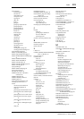
Meter Bridge Controls
A
Channel indicators
These indicators show which channels are currently being
metered: Input Channels 1–24, 25–48, 49–72, 73–96, or the Out-
put Channels (Bus Outs 1–8, Aux Sends 1–12, Matrix Sends
1–4).
B INPUT METERING POSITION button & indicators
This button is used to set the metering position for Input Chan-
nels to pre-EQ, pre-fader, or post-fader. It works in unison with
the PRE EQ, PRE FADER, and POST FADER buttons for Input
Channels on the Meter pages. The indicators show the current
setting.
C OUTPUT METERING POSITION button & indicators
This button is used to set the metering position for Output
Channels to pre-EQ, pre-fader, or post-fader. It works in unison
with the PRE EQ, PRE FADER, and POST FADER buttons for
Output Channels on the Meter pages. The indicators show the
current setting.
D PEAK HOLD button
This button is used to turn the Peak Hold function on and off. Its
indicator lights up when Peak Hold is on. It works in unison with
the PEAK HOLD buttons on the Meter pages.
E LAYER buttons
These button are used to select Layers for metering. The button
indicator for the currently selected Layer lights up. The [1–24],
[25–48], [49–72], and [73–96] buttons select the Input Layers.
The [MASTER] button selects the Master Layer. The REMOTE
[1–4] buttons select the Remote Layers. If the Meter Follow Layer
preference is on (see page 276), these Layers are selected auto-
matically when the LAYER buttons on the DM2000 are pressed.
The [1–48] button selects Input Channels 1–48, and the [49–96]
button selects Input Channels 49–96, allowing you to meter up
to 48 channels simultaneously.
F TIMECODE counter
This counter displays the current timecode position. When the
Pro Tools Remote Layer is selected, it displays the Pro Tools time-
code.
G Meters
These 12-segment LED meters display the signals levels of the
channels on the currently selected Layer.
H STEREO meters
These 32-segment meters display the signal levels of the Stereo
Out.
I CONTROL ROOM button
This button is used to display the level of the Control Room sig-
nal on the STEREO meters. Its indicator lights up when the STE-
REO meters are displaying Control Room levels.
J LAMP DIMMER knob
This knob is used to adjust the brightness of the optional LA1800
Light Goosenecks.
0
OVER
STEREO
CONTROL
ROOM
LAMP
DIMMER
234567891 12 13 14 15 16 17 18 19 2011 22 23 24
25 26 27 28 29 30
21
32 33 34 35 36 37 38 39 4031 42 43 44 45 46 47 48
49 50
41
10
51 52 53 54 55 56 57 58 59 60 61 62 63 64 65 67 68 69 70 7166 72
73
74
75
76 77 78 79 80
81 82 83 84 85 86 87 88
89 90 91 92 93 94 95 96
23456789112131415161718192011 22 23 24
21
10 25 26 27 28 29 30 32 33 34 35 36 37 38 39 4031 42 43 44 45 46 47 4841
49 50 51 52 53 54 55 56 57 58 59 60
61
62 63 64 65 67 68 69 70 7166 72 73 74 75 76 77 78 79 80 81 82 83 84 85 86 87 88 89 90 91 92 93 94 95 96
0
OVER
12
15
18
24
30
36
48
3
6
9
0
OVER
12
15
18
24
30
36
48
3
6
9
0
OVER
12
15
18
24
30
36
48
3
6
9
0
OVER
12
15
18
24
30
36
48
3
6
9
PREEQ
INPUT METERINGPOSITION
PRE FADER
POST FADER
OUTPUT METERINGPOSITION
PREEQ PRE FADER
POST FADER
MASTER
2548
4972
7396
148
4996
124
PEAK
HOLD
REMOTE 4
REMOTE 3
REMOTE 2
REMOTE 1
TIMECODE
BEAT
CLOCK
MEASURE
HMSF
2
4
6
8
10
12
14
18
24
30
36
42
48
56
72
LR
BUS
8BUS7BUS5
21
45
69
93
BUS4BUS3BUS2BUS1 BUS6 AUX12 MATRIX1 MATRIX 2 MATRIX 3 MATRIX 4AUX11AUX10AUX9AUX 8AUX7AUX6AUX5AUX4AUX3AUX 2AUX1
1
4
5
6
8
7
J
9
2
3