


1-6
Cisco ONS 15501 User Guide
78-14134-02, Release 2.0
Chapter 1 Product Overview
Cisco ONS 15501 Applications
Ring Topologies
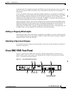
An amplified ring topology requires more fine-tuning of power for each channel or band. Figure 1-1
illustrates a hubbed ring network utilizing counter-clockwise signal transmission. All bands (A, B, C and
D) are transmitted from node 1. Node 2 terminates and transmits bands A and B; node 3 terminates and
transmits band C; and node 4 terminates and transmits band D.
Figure 1-1 Power Equalization in an Amplified Ring Network
In general, EDFAs in a ring topology should be placed so they maintain the power level at the receiver,
as well as the OSNR, of each channel. In this case, EDFAs serving as postamplifiers are located at nodes
2and4.
At node 2, the input power level of the EDFA is much higher than the input power level of the
pass-through band (bands C and D), due to the added power from bands A and B. If trunk attenuation is
employed directly before the EDFA at node 2 to keep the unit’s total input power within the required
range, the power levels of both the add bands (bands A and B) and the pass-through bands (bands C and
D) are attenuated equally. As a result, the power level of the pass-through bands is much lower than that