


1-8
Cisco ONS 15501 User Guide
78-14134-02, Release 2.0
Chapter 1 Product Overview
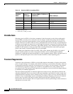
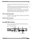
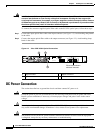
Cisco ONS 15501 Front Panel
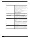
Table 1-4 Cisco ONS 15501 Front Panel Features
Feature Description
1. Output monitor (connector) Provides spectrum monitoring of the Cisco ONS 15501
output and uses an SC/UPC type bulkhead connector.
(A shutter automatically closes when the cable is removed.)
2. Output (connector) Provides output to an optical fiber cable and uses an SC/
UPC type standard connector. (A shutter automatically
closes when the cable is removed.)
3. Input (connector) Provides optical fiber cable access to the input of the
Cisco ONS 15501 and uses an SC/UPC type standard con-
nector. (This is a nonshuttered connector.)
4. Fail (red LED) Indicates a major failure, such as the pump laser, power
supply, or the temperature level.
5. Power (green LED) Indicates the unit is receiving normal operating power.
6. LOS (loss of signal) (yellow LED) Indicates a loss of input signal when the input signal falls
below the LOS threshold.
7. RS-232 (connector) Provides a console port for local monitoring of the
Cisco ONS 15501 and uses a DB-9 type female connector.
(See Appendix C, “Connector Pinouts.”) This port should
only be used for the evaluation of the unit by a trained tech-
nician. It is not designed for permanent connection.
8. Alarm out (connector) Provides four pairs of dry contacts for an optional external
alarm-monitoring system. Normally has closed contacts and
uses an RJ-45 type connector. (See Appendix C, “Connector
Pinouts.”)
9. LAN (connector) Provides Ethernet access for connecting to a remote SNMP
monitoring location, and contains two LEDs. The left LED
(green) indicates that an Ethernet connection is established.
The right LED (yellow) indicates that a signal is being trans-
mitted to the Ethernet. It uses an RJ-45 type connector.
10. Frame ground attachment Provides tapped-screw mounting holes for attaching a frame
ground lug and wiring.
11. Dual-circuit DC power input Provides two sets of DC input barrier strip terminals. The
right-hand strip terminal is for the primary DC power
wiring; the left-hand strip terminal is for an optional backup
DC power source. The left screw terminal of each strip is for
–48 VDC; the right screw terminal is for the return path.