


2-5
Cisco ONS 15501 User Guide
78-14134-02, Release 2.0
Chapter 2 Installing the Cisco ONS 15501
DC Power Connection
Warning
When installing or replacing the unit, the ground connection must always be made first and
disconnected last.
Grounding the Chassis
To connect the provided grounding lug to the tapped frame grounding holes and connect the
customer-supplied grounding wire to the DC power terminal connectors, follow these steps:
Step 1 Verify that the primary and user-optional redundant external DC power circuits are disconnected at the
source.
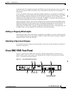
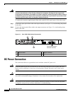
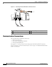
Step 2 Remove the cover from the DC power terminal connectors. Identify the two tapped frame grounding
holes at the upper right side of the Cisco ONS 15501 front panel. (See Figure 2-3.)
Step 3 Remove the two screws provided for securing the ground lug to the Cisco ONS 15501.
Step 4 Connect the 8 AWG grounding wire to the grounding lug. The other end of the wire should be suitably
grounded.
Step 5 Install the grounding lug on the Cisco ONS 15501, using the two provided screws and washers.
Step 6 Test for proper frame ground using the ohmmeter section of a digital voltmeter. Place one prod on the
Cisco ONS 15501 and the other on the frame grounding bus to which the grounding lug and grounding
wire is connected. Observe for a zero-resistance ground.
Note There is an alternate grounding point on the chassis, located on the left side of the rear panel.
Connecting the Power
To connect the power wiring to the DC power terminal connectors, follow these steps:
Step 1 Cut and strip the customer-supplied 8 AWG primary and redundant power supply wires, if necessary.
Identify the -48 VDC wire and power return wire for the primary and redundant circuit.
Step 2 Install the primary DC power wiring to the right-hand barrier strip. (See Figure 2-3.) The left-hand screw
is the -48 V connection. The right-hand screw, marked “RET,” is the ground connection.
Step 3 Install the redundant DC power wiring to the left-hand barrier strip. (See Figure 2-3.) The left-hand
screw is the -48 V connection. The right-hand screw, marked “RET,” is the ground connection.
Step 4 Replace the power connector cover.
Step 5 Apply power to the primary and redundant DC circuits.