


17
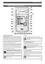
Names and Functions
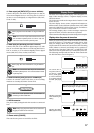
OUT
DATA
IN
DATA
SCSI
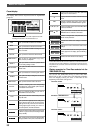
Display Section
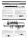
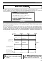
11. Data output jack [DATA OUT] (Connector: OPTICAL)
Connect this jack to the OPTICAL digital input (or adat In)
of an external digital device to save song data to a DAT or
an adat, or to record digitally to a digital device (MD, DAT,
CD-R, or adat).
Refer to page 48 for more information on using the DATA OUT
jack.
12. Data input jack [DATA IN] (Connector: OPTICAL)
Connect this jack to the OPTICAL digital output (or adat
Out) of an external digital device to load song data from a
DAT or an adat, or to record data digitally from a digital
device (MD, DAT, CD-R, or adat) to the FD-8.
Refer to page 48 for more information on using the DATA IN
jack.
13. SCSI connector [SCSI] (Connector: D-SUB 25-pin)
Connect an external current SCSI drive as the recording
media or as a backup SCSI drive for the FD-8.
Refer to the “Quick Operation Guide” for information on
connecting an external SCSI drive.
14. AC IN connector
The power cable packaged with this recorder ia connected
here.
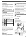
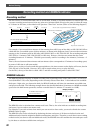
The FD-8 uses a liquid crystal display which integrates a 9-
digit/35-dot message section, 7-segment display section,
and level meters.
The level meters indicate the output level of tracks 1-8 and
stereo out L/R.
The time display shows various temporal information in
different units, such as ABS time (absolute time), MTC (MIDI
timecode), BAR/BEAT/CLK (bar/beat/clock), and makes it
easy to check the recorder’s current time.
The message display shows various messages required to
operate the FD-8, and offers interactive operation.
This section describes display functions along with examples.
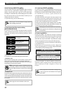
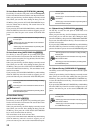
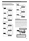
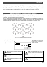
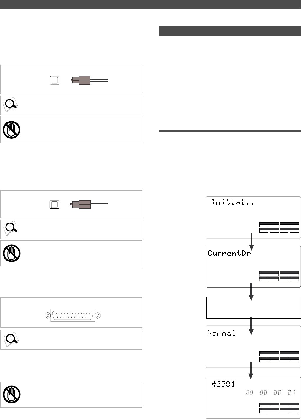
Display when the power is turned on
When you turn on the power to the FD-8 and the connected
external SCSI drive (a formatted removable disk or hard
disk), the display shows the [Initial...] message, [Current
Dr], the name of the connected current drive, then recording
mode (Master or Normal), and finally the top position of
the disk in the Time Base (ABS, MTC, or BAR/BEAT/CLK)
used in the last Program before you turned the power off.
The following example indicates that the FD-8 started with
the ABS Time Base used in Program 1.
Note:
You can save only the data recorded on the current
drive formatted in [Master] mode to a DAT or adat. You
cannot save data recorded in [Normal] mode.
Note:
You can load the data only to the current drive
formatted in [Master] mode. You cannot load data recorded
in [Normal] mode.
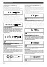
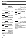
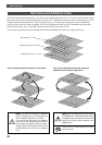
Indicating Time Base
ABS 0 (top of the disk)
The current drive is
recognized. (If the cur-
rent drive is a SCSI
device, [SCSI] lights
up. If the current drive
is an optional internal
hard disk, [IDE] lights
up.)
The name of the SCSI drive (The name is
different, depending on the type of device.)
Indicating a recording
mode used during for-
matting.
15. Power switch [POWER]
This switch turns power on and off to the FD-8.
Note:
Always plug the power cable to the recorder before
plugging the cable into the wall outlet.
DRIVE
AUTO A.PUNCH
SYNC OUT
SCSI
44.1kHz
SYNC OUT DRIVE
SCSI
AUTO A.PUNCH
44.1kHz
44.1kHz
DRIVE
AUTO A.PUNCH
SYNC OUT
SCSI
CLK
DRIVE
AUTO A.PUNCH
SYNC OUT
CLK
SCSI
SMF
PGM
ABS
44.1kHz