


9
Introduction
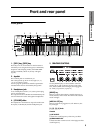
Front and rear panel
(MAIN) L/MONO, R
These are unbalanced phone jacks (☞p.12).
These are the main audio output jacks. By setting “Bus
Select” to L/R, the output from an oscillator, an inser-
tion effect, an individual drum part, or the metronome
can be output to the (MAIN) L/MONO and R jacks.
When making connections in stereo, use L/MONO
and R. When making connections in mono, use the L/
MONO jack.
(INDIVIDUAL) 1, 2
These are unbalanced phone jacks (☞p.12).
These are individual (independent) audio output jacks.
By cycling the “Bus Select” through 1, 2, 1/2 an oscilla-
tor, an insertion effect, an individual drum part, or the
metronome etc. can be assigned to be output from the
(INDIVIDUAL) 1, 2 jacks. The output from the 1, 2
jacks is not affected by the [VOLUME] slider.
6. Pedal connections
ASSIGNABLE PEDAL jack
The separately sold Korg XVP-10 EXP/VOL pedal or
EXP-2 foot controller (options) can be connected to this
jack. (
☞p.13).
Its function can be assigned in Global mode, allowing
you to use the pedal to control the volume, etc.
(
☞p.117)
ASSIGNABLE SWITCH jack
A separately sold on/off foot switch such as the Korg
PS-1 foot switch can be connected here (
☞p.13).
Its function can be assigned in Global mode, allowing
you to use the foot switch as a modulation controller,
to select programs or combinations, or to start/stop the
sequencer (
☞p.117).
DAMPER jack
A separately sold switch-type pedal such as the Korg
DS-1H damper pedal can be connected here.
If a DS-1H is connected, it will function as a half-
damper pedal. In order to ensure that the half-damper
pedal functions correctly, please adjust the polarity and
the sensitivity (
☞PG p.126, 128).
If any other switch-type pedal is connected, it will
function as a damper switch.
Set the polarity according to the pedal that you con-
nected. (
☞PG p.128)
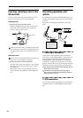
7. MIDI
MIDI IN connector
Musical data and sound settings etc. are received at
this connector.
Use this to play TR from another connected MIDI
device (
☞PG p.233).
MIDI OUT connector
Musical data and sound settings etc. are transmitted
from this connector.
Use this to control another connected MIDI device
from TR (
☞PG p.233).
If MIDI data is being transmitted from the TR via
USB to your computer, transmission from the
MIDI OUT connector is halted.
MIDI THRU connector
Musical data and sound settings etc. that are received
at the MIDI IN connector are re-transmitted without
change from the MIDI THRU connector.
You can use this to connect multiple MIDI devices via
MIDI cables (
☞PG p.233).
8. EXB-SMPL
(If the separately sold EXB-SMPL option is
installed)
These connectors are used to sample mono or stereo
audio from a mic or audio device (
☞p.35, 39), or to use
the internal effect processor to apply effects. (
☞p.115)
The MIC/LINE level select switch ([MIC/LINE]
switch) and the level adjustment knob ([LEVEL] knob)
allow a wide range of audio sources to be input, from
mic level to line level.
SCSI connector
Use a SCSI cable to connect this to a SCSI-compatible
device (hard disk drive, CD-ROM drive, etc.). (
☞ EXB-
SMPL owner’s manual)
AUDIO INPUT 1, 2 jacks
These are unbalanced phone audio input jacks. (
☞p.14)
Connect them to the OUTPUT jack(s) of your external
audio device or mic.
[LEVEL] knob
This knob adjusts the input level of the AUDIO INPUT
1, 2 jacks. (
☞p.35)
[MIC/LINE] switch
This switch selects the input level of the AUDIO
INPUT 1, 2 jacks. (
☞p.35)