115
4. External interfaces
4-2. LAN
Connect the unit and computer or the unit and an external
device
.
: An external device can be controlled from the unit.
p Use a crossover cable (category 5 or above) when
connecting the equipment directly.
p Use a straight cable (category 5 or above) when
connecting the equipment through a hub (switching hub).
p It supports plug-in software.
4-3. EDITOR
The unit can be controlled by an external device by
connecting the device to the EDITOR connector.
p It supports plug-in software.
Use it with the settings below.
Baud rate: 38400 bps
Character length: 8 bit
Parity: Odd
Stop bit: 1 bit
Flow control: None
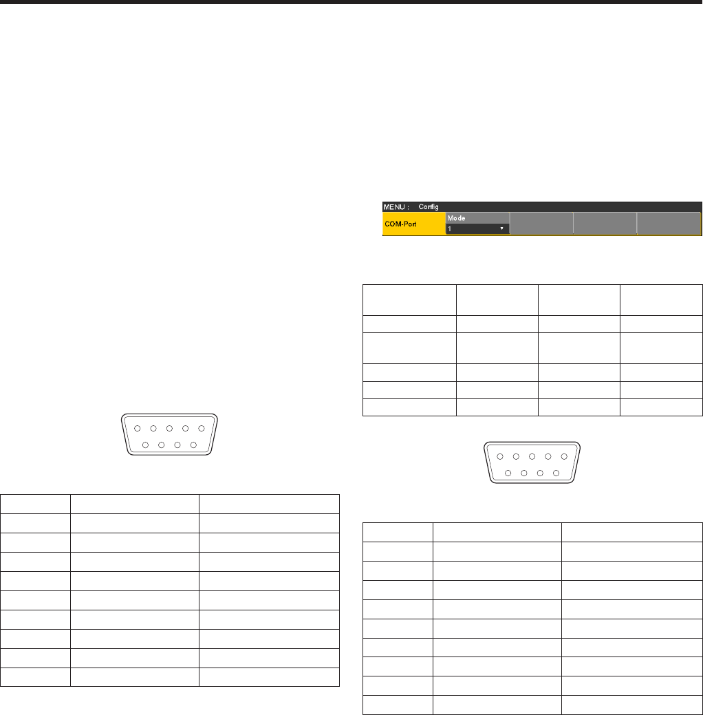
1 2 3 4 5
9 8 7 6
RS-422, D-sub 9-pin, female, inch screw
Pin No. Signal name Description of signal
1 FRAME GROUND Frame ground
2 TXD – Send data (–)
3 RXD + Receive data (+)
4 GROUND Ground
5 NC Not used
6 GROUND Ground
7 TXD + Send data (+)
8 RXD – Receive data (–)
9 FRAME GROUND Frame ground
4-4. COM
An external device can be controlled from the unit.
p It supports plug-in software.
The communication system can be selected using the setting
menu.
1Press the s button to light its indicator, and display the
Config menu.
2Use [F1] to display the COM-Port sub menu.
3Use [F2] to select the communication system using the
Mode item.
Mode: 1
(default setting)
Mode: 2 Mode: 3
Baud rate 9600 bps 38400 bps 38400 bps
Character
length
8 bit 8 bit 8 bit
Parity None Odd None
Stop bit 1 bit 1 bit 1 bit
Flow control None None None
1 2 3 4 5
9 8 7 6
RS-422, D-sub 9-pin, female, inch screw
Pin No. Signal name Description of signal
1 FRAME GROUND Frame ground
2 RXD – Receive data (–)
3 TXD + Send data (+)
4 GROUND Ground
5 NC Not used
6 GROUND Ground
7 RXD + Receive data (+)
8 TXD – Send data (–)
9 FRAME GROUND Frame ground
p The pin assignment is different from that of the EDITOR
connector.


