


AD9912
Rev. D | Page 16 of 40
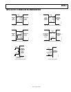
THEORY OF OPERATION
06763-031
DDS/DAC
FREQUENCY
TUNING WORD
÷S
2×
DIGITAL SYNTHESIS CORE
CONTROL
LOGIC
LOW NOISE
CLOCK
MULTIPLIER
AMP
SYSCLK PORT
EXTERNAL
ANALOG
LOW-PASS
FILTER
EXTERNAL
LOOP
FILTER
DIGITAL
INTERFACE
SYSCLK SYSCLKBS1 TO S4
FDBK_IN
FDBK_INB
DAC_OUT
DAC_OUTB
OUT
OUTB
OUT_CMOS
CONFIGURATION
LOGIC
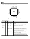
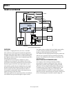
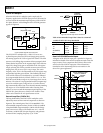
Figure 39. Detailed Block Diagram
OVERVIEW
The AD9912 is a high performance, low noise, 14-bit DDS
clock synthesizer with integrated comparators for applications
desiring an agile, finely tuned square or sinusoidal output signal.
A digitally controlled oscillator (DCO) is implemented using a
direct digital synthesizer (DDS) with an integrated output DAC,
clocked by the system clock.
A bypassable PLL-based frequency multiplier is present,
enabling use of an inexpensive, low frequency source for the
system clock. For best jitter performance, the system clock PLL
should be bypassed, and a low noise, high frequency system
clock should be provided directly. Sampling theory sets an upper
bound for the DDS output frequency at 50% of f
S
(where f
S
is
the DAC sample rate), but a practical limitation of 40% of
f
S
is generally recommended to allow for the selectivity of the
required off-chip reconstruction filter.
The output signal from the reconstruction filter can be fed back
to the AD9912 to be processed through the output circuitry.
The output circuitry includes HSTL and CMOS output buffers,
as well as a frequency doubler for applications that need
frequencies above the Nyquist level of the DDS.
The AD9912 also offers preprogrammed frequency profiles that
allow the user to generate frequencies without programming
the part. The individual functional blocks are described in the
following sections.
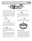
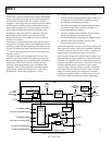
DIRECT DIGITAL SYNTHESIZER (DDS)
The frequency of the sinusoid generated by the DDS is
determined by a frequency tuning word (FTW), which is a
digital (that is, numeric) value. Unlike an analog sinusoidal
generator, a DDS uses digital building blocks and operates as
a sampled system. Thus, it requires a sampling clock (f
S
) that
serves as the fundamental timing source of the DDS. The
accumulator behaves as a modulo-2
48
counter with a program-
mable step size that is determined by the frequency tuning word
(FTW). A block diagram of the DDS is shown in Figure 40.