


AD9912
Rev. D | Page 32 of 40
I/O REGISTER DESCRIPTIONS
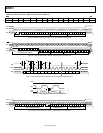
SERIAL PORT CONFIGURATION (REGISTER 0x0000 TO REGISTER 0x0005)
Register 0x0000—Serial Port Configuration
Table 13.
Bits Bit Name Description
[7:4] These bits are the mirror image of Bits[3:0].
3 Long instruction Read-only; the AD9912 supports only long instructions.
2 Soft reset Resets register map, except for Register 0x0000. Setting this bit forces a soft reset, meaning that S1 to
S4 are not tristated, nor is their state read when this bit is cleared. The AD9912 assumes the values of
S1 to S4 that were present during the last hard reset. This bit is not self-clearing, and all other registers
are restored to their default values after a soft reset.
1 LSB first Sets bit order for serial port.
1 = LSB first.
0 = MSB first. I/O update must occur for the MSB first to take effect.
0 SDO active Enables SDO pin.
1 = SDO pin enabled (4-wire serial port mode).
0 = 3-wire mode.
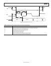
Register 0x0001—Reserved
Register 0x0002 and Register 0x0003—Part ID (Read-Only)
Register 0x0004—Serial Options
Table 14.
Bits Bit Name Description
0 Read buffer register For buffered registers, serial port readback reads from actual (active) registers instead of the buffer.
1 = reads the buffered values that take effect during the next I/O update.
0 = reads values that are currently in effect.
Register 0x0005—Serial Options (Self Clearing)
Table 15.
Bits Bit Name Description
0 Register update Software access to the register update pin function. Writing a 1 to this bit is identical to performing
an I/O update.
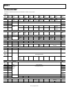
POWER-DOWN AND RESET (REGISTER 0x0010 TO REGISTER 0x0013)
Register 0x0010—Power-Down and Enable
Power-up default is defined by the start-up pins.
Table 16.
Bits Bit Name Description
7 PD HSTL driver Powers down HSTL output driver.
1 = HSTL driver powered down.
6 Enable CMOS driver Powers up CMOS output driver.
1 = CMOS driver on.
5 Enable output doubler Powers up output clock generator doubler. Output doubler must still be enabled in Register 0x0200.
4 PD SYSCLK PLL System clock multiplier power-down.
1 = system clock multiplier powered down.
If the S4 pin is tied high at power-up or reset, this bit is set, and the default value for Register 0x0010
is D0, not C0.
1 Full PD Setting this bit is identical to activating the PD pin and puts all blocks (except serial port) into power-
down mode. SYSCLK is turned off.
0 Digital PD Removes clock from most of digital section; leave serial port usable. In contrast to full PD, setting this
bit does not debias inputs, allowing for quick wake-up.