


AD9912
Rev. D | Page 22 of 40
Although the worst spurs tend to be harmonic in origin, the fact
that the DAC is part of a sampled system results in the possibility
of spurs appearing in the output spectrum that are not harmoni-
cally related to the fundamental. For example, if the DAC is
sampled at 1 GHz and generates an output sinusoid of 170 MHz,
the fifth harmonic would normally be at 850 MHz. However,
because of the sampling process, this spur appears at 150 MHz,
only 20 MHz away from the fundamental. Therefore, when
attempting to reduce DAC spurs it is important to know the
actual location of the harmonic spur in the DAC output
spectrum based on the DAC sample rate so that its harmonic
number can be reduced.
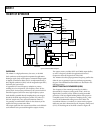
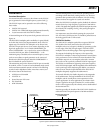
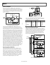
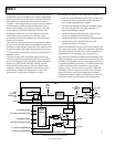
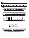
The mechanics of performing harmonic spur reduction is shown
in Figure 48. It essentially consists of two additional DDS cores
operating in parallel with the original DDS. This enables the user
to reduce two different harmonic spurs from the second to the
15
th
with nine bits of phase offset control (±π) and eight bits of
amplitude control.
The dynamic range of the cancellation signal is further aug-
mented by a gain bit associated with each channel. When this
bit is set, the magnitude of the cancellation signal is doubled by
employing a 1-bit left-shift of the data. However, the shift
operation reduces the granularity of the cancellation signal
magnitude. The full-scale amplitude of a cancellation spur is
approximately −60 dBc when the gain bit is a Logic 0 and
approximately −54 dBc when the gain bit is a Logic 1.
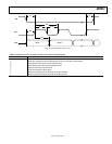
The procedure for tuning the spur reduction is as follows:
1. Determine which offending harmonic spur to reduce and
its amplitude. Enter that harmonic number into Bit 0 to
Bit 3 of Register 0x0500/Register 0x0505.
2. Turn off the fundamental by setting Bit 7 of Register 0x0013
and enable the SpurKiller channel by setting Bit 7 of
Register 0x0500/Register 0x0505.
3. Adjust the amplitude of the SpurKiller channel so that it
matches the amplitude of the offending spur.
4. Turn the fundamental on by clearing Bit 7 of Register 0x0013.
5. Adjust the phase of the SpurKiller channel so that
maximum interference is achieved.
Note that the SpurKiller setting is sensitive to the loading of the
DAC output pins, and that a DDS reset is required if a SpurKiller
channel is turned off. The DDS can be reset by setting Bit 0 of
Register 0x0012, and resetting the part is not necessary.
The performance improvement offered by this technique varies
widely and depends on the conditions used. Given this extreme
variability, it is impossible to define a meaningful specification
to guarantee SpurKiller performance. Current data indicate that
a 6 dB to 8 dB improvement is possible for a given output
frequency using a common setting over process, temperature,
and voltage. There are frequencies, however, where a common
setting can result in much greater improvement. Manually
adjusting the SpurKiller settings on individual parts can result
in more than 30 dB of spurious performance improvement.
06763-040
0
1
1
0
14
1419
19
QD
48
14
DAC
(14-BIT)
DAC_OUT
DAC_OUTB
4
9
4
9
8
8
SHIFT
1
0
SHIFT
HEADROOM
CORRECTION
HARMONIC SPUR CANCELLATION
CH1 HARMONIC NUMBER
CH1 CANCELLATION PHASE OFFSET
CH2 HARMONIC NUMBER
CH2 CANCELLATION PHASE OFFSET
CH1 CANCELLATION MAGNITUDE
CH2 CANCELLATION MAGNITUDE
CH1 GAIN
CH2 GAIN
SPUR
CANCELLATION
ENABLE
ANGLE TO
AMPLITUDE
CONVERSION
DDS
PHASE
OFFSET
14
48
48-BIT ACCUMULATOR
DDS
48-BIT
FREQUENCY
TURNING WORD
(FTW)
SYSCLK
2-CHANNEL
HARMONIC
FREQUENCY
GENERATOR
CH1
CH2
DAC_RSET
DAC I-SET
REGISTERS
AND LOGIC
Figure 48. Spur Reduction Circuit Diagram