


E-8
Contents
Conventions
This manual describes how to setup the CM-2600d/2500d which the firmware version is 1.40 or higher
and use it to take measurements.
• Organization
The CM-2600d/2500d (Ver. 1.30 or higher) supports two types of the target mode, “linked to each data.”
and “defined in COND.”; the procedure and details for these types varies slightly.
This manual describes the procedures for the default target mode, which is “linked to each data.”. It only
includes information for the “defined in COND.” mode where it differs from the default.
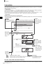
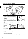
• Page layout
Symbols used in this manual are explained below.
*Note that the page shown in the illustration is for explanatory purposes only, and is not an actual page
from this manual.
60
Setting an Environmental Condition
Up to six sets of conditions (COND 1 to COND 6) can be set. Since the instrument will perform meas-
urement according to the selected condition, conditions must be set prior to start of measurement.
The following nine condition items can be set:
• A setting can be made for the currently highlighted item. To confirm the setting, press AA. The next item will
be highlighted automatically.
• The items (1) to (9) must be set in this order. If incorrect settings have been made, you must start once again
from item (1).
[Setting Procedure]
<FILE> screen
1
Turn BB to select “SEL”, then press AA.
• “SEL” can be selected in page 1/2 only.
2
Turn BB to select the desired setting, then press AA.
<Settings>
• M/I+E: ø8 mm, simultaneous measurement of SCI and SCE
• M/SCI: ø8 mm, SCI
• M/SCE: ø8 mm, SCE
• The measurement area that suits the target mask used for measurement or the setting of the lens posi-
tion selector switch must be selected.
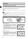
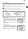
3
Direct the specimen measuring port to the specimen.
• If necessary, slide the viewfinder lever to check the position of the specimen.
M
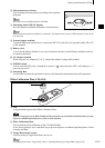
emo
Gives useful Informa-
tion and additional ex-
planations.
Note
Gives the points that you should know to perform op-
erations correctly. Make sure that you read the notes.
Procedure
Shows the oper-
ating procedure.
C............ Indicates the <MEAS.> button.
B....... Indicates request to turn the navigation wheel to the right or left.
A....... Indicates request to press the navigation wheel.
Start screen
Shows the screen
from which oper-
ation must be
started.
Screen
Shows the con-
tents of the screen
in effect when the
given operation is
carried out.
Settings
Gives the range
and explanation
of the values to
be set in this
screen.
TIP (screen)
Gives explanation
about the screen
and operations that
can be carried out
from this screen.
Screen note
Gives the points to note on
the operations to be per-
formed from this screen.
For the version of the instrument firmware
The version of the instrument firmware can be confirmed on the screen which is displayed first after
switching power on.