E-116
Principles of Measurement
Simultaneous SCI/SCE Measurement
The CM-2600d/2500d employs simultaneous SCI/SCE measurement method.
With the conventional models, SCI (Specular Component Included) and SCE (Specular Component Ex-
cluded) need to be switched mechanically by opening/closing the optical trap provided inside the inte-
grating sphere.
This means mechanical switching has to be made each time the mode is switched from SCI to SCE or
vice versa, and it is not possible to start measurement in the new mode until switching is complete.
With the CM-2600d/2500d, both SCI and SCE data can be obtained simultaneously by calculating the
data obtained by two illuminantions.
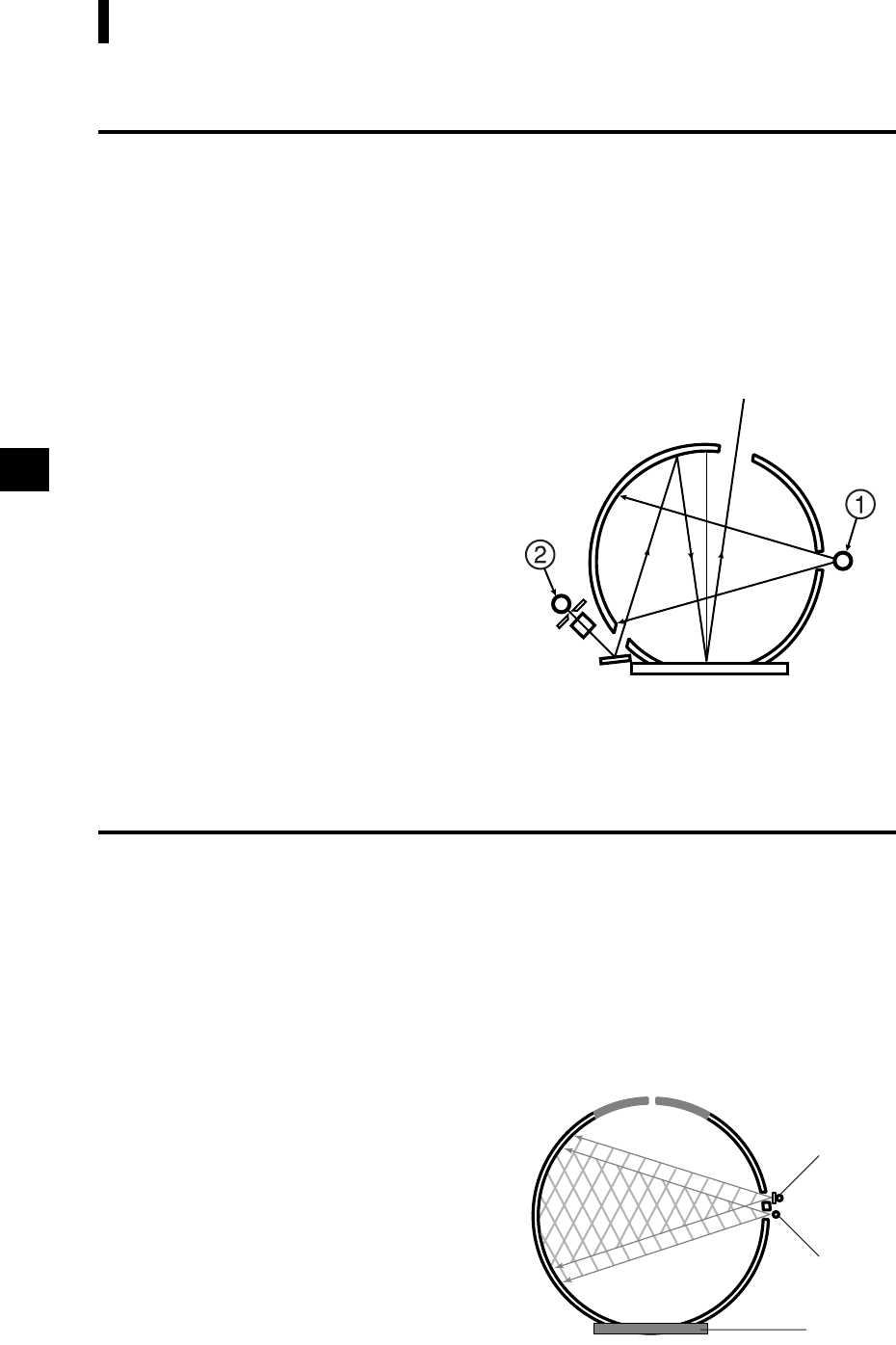
Simultaneous SCI/SCE Measurement Method
To illuminating/viewing system
specimen
Two light sources 1 and 2 are located as shown in
the figure, and light source 1 flashes first.
Light source 1 is the diffused illumination type,
and SCI measured data can be obtained as it
flashes.
Then, light source 2 flashes next.
Light source 2 is provided for numeric control
of the specular component. The data (i.e. amount
of light reflected specularly from the surface of
the specimen) obtained when this light source
flashes and that obtained when light source 1
flashed are used to calculate SCE data.
By carrying out the above measurement and calculation during a single measurement, both SCI and SCE
data can be obtained simultaneously without mechanical switching that is required in the case of the con
-
ventional models.
UV Control
With the CM-2600d, two light sources, one contains UV (Ultraviolet) component and the other doesn’t,
flash sequentially and a desired illumination containing the specific UV intensity is virtually created by
calculation based on the two measured numeric data sets. In case of conventional models with a single
light source, the position of UV cutoff filter in the flux from the light source is mechanically adjusted to
control the UV intensity. The adjustment of the filter position requires repeated operations.
Since the UV control in CM-2600d is performed by the calculation based on the data measured using two
light sources, it is completed in a instance and the deterioration of a fluorescent standard which often hap
-
pens in conventional models due to the repeated illumination during adjustment is prevented.
Mechanism of UV Control
light source 2
light source 1
specimen
Two light sources 1 (without UV cutoff filter) and
2 (with a UV cutoff filter) are located as shown be
-
low. Light sources 1 and 2 flash sequentially with-
in the measurement time of approximately 2 seconds.
As a result, the spectral reflectance data with and
without UV component can be obtained, based on
which the calculation for UV intensity control is per
-
formed. These two spectral reflectance data are com-
pared/merged to obtain the UV intensity correction
data.


