


124
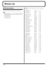
Effects List
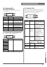
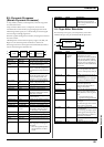
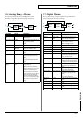
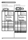
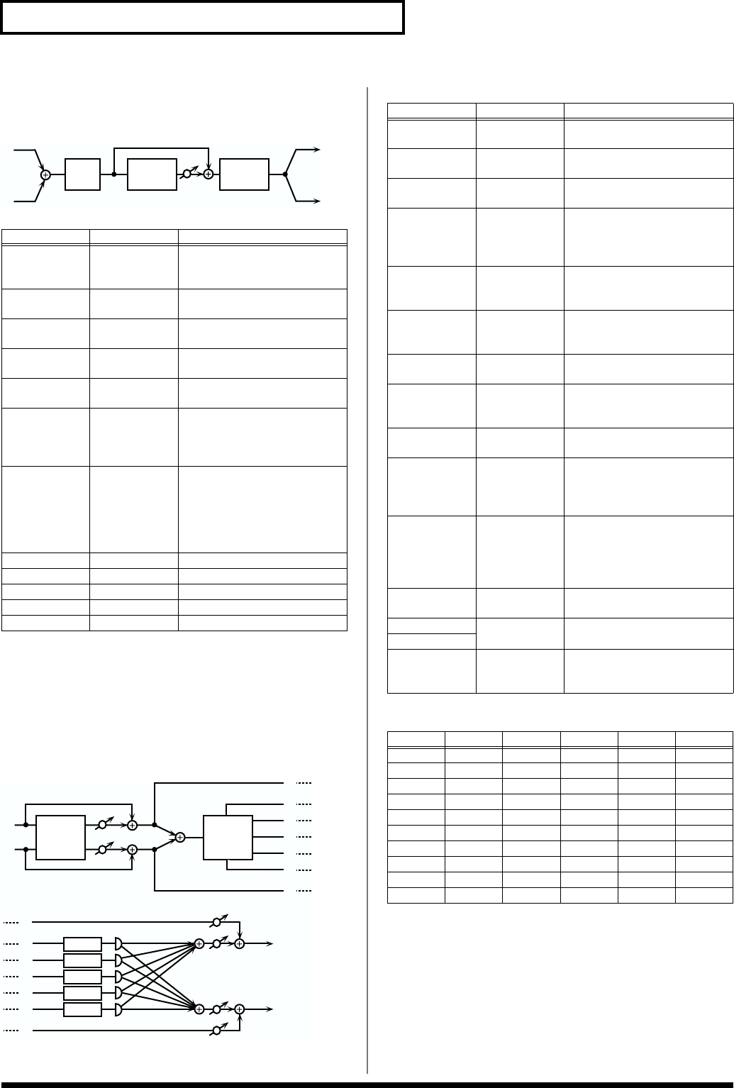
14: Vocal Echo
This effect simulates a karaoke echo.
fig.MFX-14
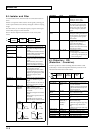
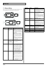
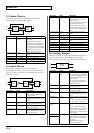
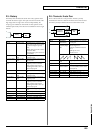
15: Band Pass Delay
This is a delay with a band pass filter (a filter that outputs only a
specified frequency range) on each of five delays. A phaser is
included before the delay. Phaser is an effect that adds a phase-
shifted sound to the original sound to create time-varying change,
modulating the sound.
fig.MFX-15
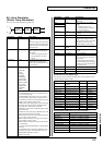
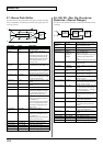
Delay Pan Type
Parameter Value Description
Delay Time #1 0–650 ms, note Adjusts the delay time from the
direct sound until the delay
sound is heard.
Pre LPF Freq 500–15000 Hz,
THRU
Sets the filter’s cutoff frequency
(THRU: no filter is used)
Mod Rate 0.05–10.0 Hz,
note
Specifies the modulation speed
of the modulation effect.
Mod Depth 0–127 Specifies the modulation depth
of the modulation effect.
Diffusion 0–100 Specifies the spaciousness of the
delay sound.
Feedback #2 -98– +98 % Adjusts the proportion of the de-
lay sound that is fed back into
the effect. Negative (-) settings
will invert the phase.
Hi Damp Freq 500–15000 Hz,
THRU
Adjusts the frequency above
which sound fed back to the ef-
fect will be cut.
High Damp, by attenuating the
higher frequencies first, makes
the delay sound more natural.
Echo Level #3 0–127 Volume of the echo sound
Ps Low Freq 50–4000 Hz Frequency of the low range
Ps Low Gain -15– +15 dB Gain of the low range
Ps Hi Freq 2000–20000 Hz Frequency of the high range
Ps Hi Gain -15– +15 dB Gain of the high range
2-Band
EQ
L
R
LPF ECHO
L
R
Phaser Delay
1
2
3
4
5
BPF 1
BPF 2
BPF 3
BPF 4
BPF 5
1
2
3
4
5
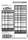
Parameter Value Description
Phaser Manual 0–127 Specifies the center frequency at
which the sound is modulated.
Phaser Rate 0.05–10.0 Hz,
note
Specifies the frequency of mod-
ulation.
Phaser Depth 0–127 Specifies the depth of modula-
tion.
Phaser Reso-
nance
0–127 Specifies the amount of feed-
back for the phaser.
Higher settings will give the
sound a stronger character.
Phaser Mix Lev-
el
0–127 Specifies the volume of the
phase-shifted sound, relative to
the direct sound.
Delay Time 0–1300 ms, note Adjusts the delay time from the
direct sound until the each delay
sound is heard.
Fbk Dly Time 0–1300 ms, note Adjusts the delay time for the
feedback sound.
Dly Time Dev 0–1300 ms, note Specifies the differences in delay
time for each of the delay
sounds.
Delay Level 0–127 Adjusts the volume of each de-
lay sound.
Delay Feedback
#1
-98– +98 % Adjusts the proportion of the de-
lay sound that is fed back into
the effect. Negative (-) settings
will invert the phase.
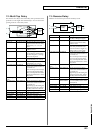
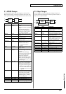
Delay Pan Type 1–10 Specifies the pan of each delay
sound.
Ten settings are provided as var-
ious panning combinations of
the delay sounds (see below).
BPF 1–5 Freq 50–20000 Hz Sets the center frequency for
each band pass filter (1–5).
BPF 1/2 Q 0.3–24.0 Specify the output bandwidth
for each band pass filter (1-5).
BPF 3/4/5 Q
Balance #2 DRY100:0WET–
DRY0:100WET
Volume balance between the di-
rect sound (DRY) and the delay
sound (WET)
Values Dly 1 Dly 2 Dly 3 Dly 4 Dly 5
1 L63 L32 0 32R 63R
2 L63 32R L32 63R 0
3 L63 63R L32 32R 0
4 32R L32 L63 0 63R
5 63R 0 L63 L32 32R
6 L32 32R L63 63R 0
7 0 63R L63 32R L32
8 0 63R L32 32R L63
9 0 32R L32 63R L63
10 63R 32R 0 L32 L63