


Owner’s Manual
Optional Plug-in Board installation Installation precautions
99
Appendix
Optional Plug-in Board
installation
A variety of optional Plug-in Boards (page 52) sold separately let
you expand the Voice library of your instrument.
The following types of Plug-in Boards can be used with your
instrument.
• PLG150-AN • PLG150-DX
• PLG150-PF • PLG150-DR
• PLG150-AP • PLG150-PC
• PLG150-VL • PLG100-XG
Installation precautions
Before installing the optional hardware, make sure you have a
Philips screwdriver.
• Before beginning installation, switch off the power to the MOTIF-RACK
ES and connected peripherals, and unplug them from the power outlet.
Then remove all cables connecting the MOTIF-RACK ES to other
devices. (Leaving the power cord connected while working can result in
electric shock. Leaving other cables connected can interfere with work.)
• Be careful not to drop any screws inside the instrument during installation
(this can be prevented by keeping the optional units and cover away
from the instrument while attaching). If this does happen, be sure to
remove the screw(s) from inside the unit before turning the power on.
Loose screws inside the instrument can cause improper operation or
serious damage. If you are unable to retrieve a dropped screw, consult
your Yamaha dealer for advice.
• Install the optional units carefully as described in the procedure below.
Improper installation can cause shorts which may result in irreparable
damage and pose a fire hazard.
• Do not disassemble, modify, or apply excessive force to board areas and
connectors on optional units. Bending or tampering with boards and
connectors may lead to electric shock, fire, or equipment failures.
• It is recommended that you wear gloves to protect your hands from
metallic projections on optional units and other components. Touching
leads or connectors with bare hands may cause finger cuts, and may
also result in poor electrical contact or electrostatic damage.
• Handle the optional units with care. Dropping or subjecting them to any
kind of shock may cause damage or result in a malfunction.
• Be careful of static electricity. Static electricity discharge can damage
the IC chips on the Plug-in Board. Before you handle the optional Plug-in
Board, to reduce the possibility of static electricity, touch the metal parts
other than the painted area or a ground wire on the devices that are
grounded.
• Do not touch the exposed metal parts in the circuit board. Touching
these parts may result in a faulty contact.
• When moving a cable, be careful not to let it catch on the circuit Plug-in
Board. Forcing the cable in anyway may cut the cable, cause damage, or
result in a malfunction.
• Be careful not to misplace any of the screws since all of them are used.
• Do not use any screws other than what are installed on the instrument.
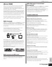
Installing the Plug-in Board
1.
Turn the MOTIF-RACK ES power off, and disconnect the
power cord.
Also, if the MOTIF-RACK ES is connected with other external
device(s), disconnect the device(s).
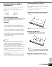
2. Move to a position facing the front panel of the device,
and remove the screws (six flat-head screws) from the
Plug-in Board cover at the top panel with a Phillips
screwdriver.
n Keep the removed (6) screws in a safe place. They will be used when
attaching the Plug-in Board cover to the device again.
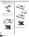
3. Remove the Plug-in Board cover.
Plug-in Board plate appears. Two Plug-in Boards can be
accommodated: PLG1 at the right and PLG2 at the left.
n The Multi-part Plug-in Board (PLG100-XG) can be installed only to PLG2.
When installing the optional Plug-in Board (from when you remove the cover
to when the cover is replaced securely) all operations must be done with the
AC power cord disconnected.
4. Take out the Plug-in Board from the anti-static bag.
When installing the board, the side with a connector and ICs must
be on top.
WARNING
CAUTION
PLG2
PLG1
CAUTION