


20
ACCESS
PHANTOM
OPTICAL
58
57
59
60
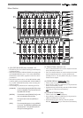
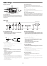
TIP:
AUX1
To Effect 1
To Effect 2
RING:
AUX2
GND
ST OUTAUX SEND
RL
IN OUT
MIDI DIGITAL / DATA FOOT SW
IN OUT
SCSI POWER AC-IN
OPTICAL
61 63 65 6664 67 68 69 7062
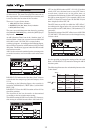
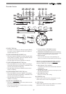
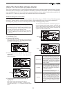
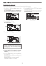
Display Section
57. [ACCESS] LED
This LED lights ON when the internal hard disk drive or
external SCSI device for backup purposes is writing or
reading data.
58. [PHANTOM] LED
This lights ON when the phantom power is ON.
The phantom power is turned ON/OFF with the setup
mode.
59. LCD (Liquid Crystal Display)
The recorder and mixer status and parameters are shown
on the LCD.
60. Contrast Adjusting Knob
This is used to adjust the contrast (difference in
brightness) of the LCD. Increase or decrease the contrast
by turning it clockwise or counterclockwise, respectively.
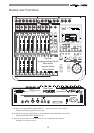
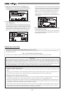
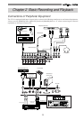
Rear Panel
65. [DIGITAL/DATA IN] Jack
* Connect to OPTICAL DIGITAL OUT (S/P DIF) or adat
DIGITAL OUT of an external digital device for signal
input to the VF-16.
* This is used to load DAT/adat song data.
* Connector: Square optical
66. [DIGITAL/DATA OUT] Jack
* Connect to OPTICAL DIGITAL IN (S/P DIF) or adat
DIGITAL IN of an external digital device for signal
output from the VF-16.
* This is used to save DAT/adat song data.
* Connector: Square optical
67. [FOOT SW] Jack
* Punch IN/OUT option by connecting the Fostex Model
8051 foot switch (unlatched type).
68. [SCSI] Connector
* This is where external SCSI devices (SCSI ID to 6) for
backup purposes are connected.
* Connector: Half pitch D-sub, 50-pin, female
69. [POWER] switch
* This turns ON/OFF the power of the VF-16.
70. [AC IN] Jack
* This is where the accessory power cable is inserted.
For more details, refer to the respective instructions
of each item.
62. [ST OUT-L/R] Jack
* Master recorders and other devices are connected to
output stereo L/R signals.
* Standard Output Level: -10dBV
* Connector: RCA (pin)
63. [MIDI IN] Jack
* Connect to the MIDI OUT jack of an external MIDI
device.
* MIDI control signals such as MMC (MIDI Machine
Control) is mainly input.
* Connector: DIN 5 PIN
64. [MIDI OUT] Jack
* Connect to the MIDI IN jack of an external MIDI device.
* MIDI synchronization signals such as MTC (MIDI Time
Code) and MIDI clock signals & song position pointers
are mainly output.
* Connector: DIN 5 PIN
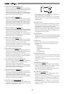
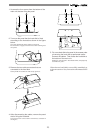
61. [AUX SEND-1/2] Jack
* External effector or other devices are connected to
output the AUX SEND 1/2 signals.
* Standard Output Level: -10dBV
* Use a Y-cable, as shown below, to connect an external
effector since the ø6 TRS Phones jack is used.