


MPCMM0002 CMM—Getting Started
Intel NetStructure
®
MPCMM0002 Chassis Management Module
Hardware TPS July 2007
14 Order Number: 309247-004US
3.1.1 Quick Start
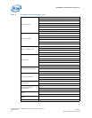
1. Open the packing material, find the packing list, and ensure that all the necessary
components are present for the Intel NetStructure
®
MPCMM0002 CMM.
2. Take the MPCMM0002 CMM to the chassis in which it will be installed.
3. Following standard ESD protection procedures, remove the CMM from its anti-static
bag.
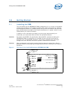
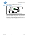
4. Insert the management module into the card guides for the dedicated CMM slot.
Follow the chassis manufacturer’s or system vendor’s directions for the proper
orientation of the CMM.
5. As the CMM is being pushed into the slot, keep the ejector handle open until it
engages with the card guide. Ensure the alignment pins on the faceplate engage
the receptacles on the card cage. When the ejector handle engages, rotate the
ejector handle toward the faceplate until the card is fully seated.
6. Use a screwdriver or pair of pliers to tighten the retention screws on both ends of
the faceplate.
7. If the chassis power is on, the CMM will turn on automatically.
8. Connect the appropriate cables to the front or rear serial port, LAN ports. Connect
the telco alarm connector, if desired.
9. If a second CMM is to be installed in the chassis, follow the same instructions in this
procedure.
To remove the CMM:
1. Loosen the retention screws with a screw driver (Type#1 Philips head screw
driver).
2. Pull the ejector away from the faceplate (unlatch condition for ejector) enough to
ensure that the blue LED on the faceplate begins to flash. At this stage, the CMM
remains attached to the chassis (the backplane connector of CMM is still mated
with the chassis’s connector).
3. When the blue hot swap LED turns solid blue, pull the ejector farther out in order to
eject the CMM from the chassis.
Note: The hot swap LED will turn solid blue only when the redundancy feature is fully
enabled.