


Intel NetStructure
®
MPCMM0002 Chassis Management Module
July 2007 Hardware TPS
Order Number: 309247-004US 57
Thermals—MPCMM0002 CMM
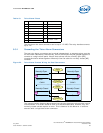
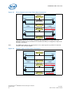
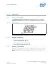
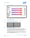
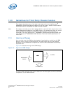
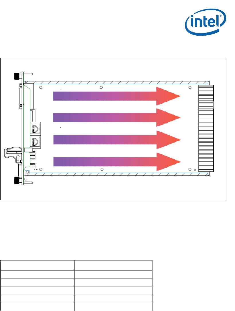
It may be necessary to enclose the area around a CMM when cooled front-to-back to
ensure that air is properly channeled across the board and evenly distributed.
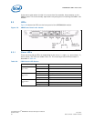
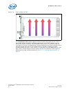
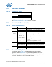
11.4 Airflow Requirements
General airflow requirements for the CMM are shown in Table 23.
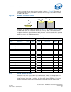
11.5 Board Resistance Curve
As described in Chapter 5 of the PICMG* 3.0 specification, all board vendors are
required to provide a flow pressure curve for their board along with the airflow
requirements for specific wattages. This enables system integrators to compare the slot
resistance curves of their shelves with the resistance and airflow requirements of their
blades to approximate whether a given chassis can cool a particular blade.
The MPCMM0002 CMM is not subject to this requirement because the board is not an
AdvancedTCA standard form factor. Flow pressure curves will vary widely depending
upon location of the MPCMM0002 CMM in a chassis and the type/amount of airflow
across the MPCMM0002 CMM at that location.
Figure 31. Front-to-Back Air Flow
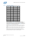
Table 23. Typical Airflow and Cooling Requirements
Category CMMs
Required LFM 180 LFM (54.864 m/min)
Required CFM 5 CFM (0.1416 m
3
/min) per CMM
Typical Heat Dissipation 21 W per CMM
Maximum Heat Dissipation 28 W per CMM
Approximate Airflow Resistance 0.2 in.-H
2
O (~46 Pa)