


MPCMM0002 CMM—Guidelines for Third Party Chassis Vendors
Intel NetStructure
®
MPCMM0002 Chassis Management Module
Hardware TPS July 2007
66 Order Number: 309247-004US
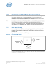
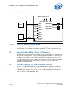
13.3 GPIO Pins
As shown in Figure 33, there are 10 GPIO pins (signal names GPIO1 through GPIO10),
which can be configured by software for a set of predefined usage types such as
detecting presence of a device, controlling LEDs, controlling push buttons, and reading
single bit values for each pin. Limited support for configuration and use of dedicated I/
O Signals and 10 additional GPIO signals is available in firmware versions starting from
6.1. More details on configuration of these signals are available in the Intel
NetStructure
®
MPCMM0001 Chassis Management Module and Intel NetStructure
®
MPCMM0002 CMM Software Technical Product Specification.
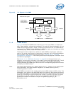
13.3.1 Dedicated I/O Pins
Some of the I/O pins shown in Figure 33 have a dedicated purpose, but some of them
are GPIO pins which could be used for other purposes. As shown in Figure 33, there are
ten dedicated I/O pins:
• Seven are wired to the GPIO pins of FPGA1. These GPIOs can be reconfigured for
different uses. The corresponding signal names are: BP_AFLED[1:2], BP_AFPRES#,
FRU0_STATUS[0:1], and FRU1_STATUS[0:1]. A detailed description of these
signals can be found in Section 7.1.2, “CMM Data Connector” on page 36.
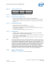
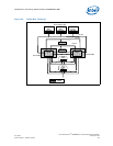
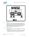
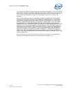
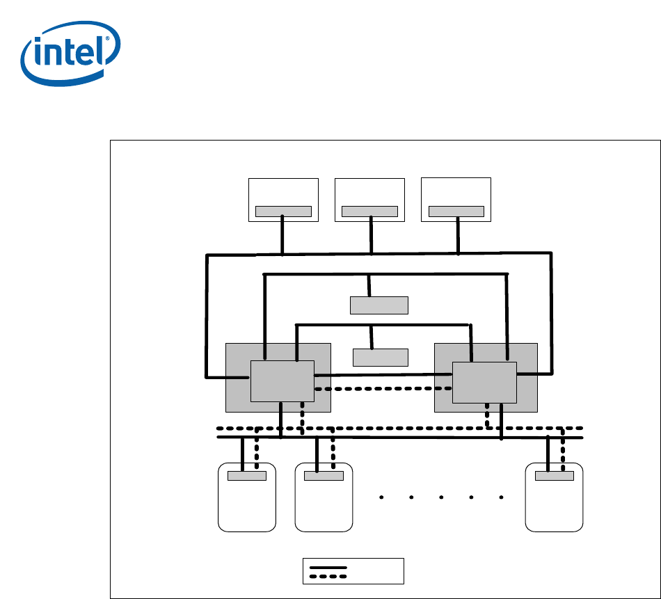
Figure 35. Shared Bus Topology
a
a. The ADM1026 shown in the PEMs and the fan tray is just one possible I
2
C controller that can be used.
FPGAs
ATCA
Board1
IPMC
ATCA
Board2
IPMC
Active ShMC
ATCA
BoardN
IPMC
Standby ShMC
FPGAs
Shelf FRU1
Shelf FRU2
Non-Intelligent FRUs
PEM1
ADM 1026
PEM1
ADM 1026
Fantray1
ADM 1026
IPMB A
IPMB B
i2C Bus
i2C Bus
i2C Bus