


Intel NetStructure
®
MPCMM0002 Chassis Management Module
July 2007 Hardware TPS
Order Number: 309247-004US 49
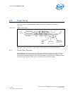
Front Panel—MPCMM0002 CMM
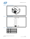
The signals on the alarm connector can be up to –72 VDC. The relay handles currents
up to 1 A.
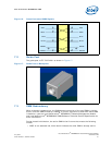
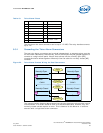
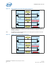
9.3.1 Cascading the Telco Alarm Connectors
The two telco alarm connectors can be wired independently to separate alarm controls
for maximum redundancy. Alternatively, the two connectors may be ganged together to
connect to a single alarm panel. Alarms that activate off the normally open [NO]
contacts should be wired together differently than the cable for normally closed [NC]
contacts.
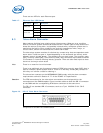
The interconnection diagram above shows how the two signals are wired under normal
circumstances. In a failure scenario such as a disconnected cable, however, only the
normally closed contact reports an error. This is identical to the behavior in a failure
scenario with a single telco alarm connector.
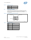
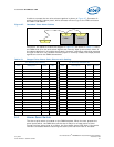
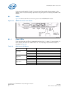
Table 18. Telco Alarm Pinout
Pin Description Pin Description
1 MinorReset + 9 MinorAlarm - NC
2 MinorReset - 10 MinorAlarm - COM
3 MajorReset + 11 MajorAlarm - NO
4 MajorReset - 12 MajorAlarm - NC
5 CriticalAlarm - NO 13 MajorAlarm - COM
6 CriticalAlarm - NC 14 PwrAlarm - NO
7 CriticalAlarm - COM
15 PwrAlarm - COM
8 MinorAlarm - NO
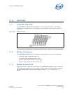
Figure 24. Telco Alarm Contact Wiring for Dual Connectors
CMM 2CMM 1
Normally Open
Common
Normally Open
Common
Normally Closed
Common
Normally Closed
Common
Common
Alarm
(Normally Closed)
Common
Alarm
(Normally Open)
NC
NO
NC
NO