


Intel NetStructure
®
MPCMM0002 Chassis Management Module
July 2007 Hardware TPS
Order Number: 309247-004US 63
Guidelines for Third Party Chassis Vendors—MPCMM0002 CMM
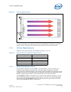
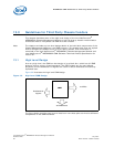
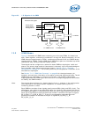
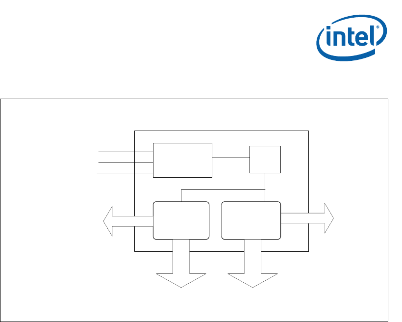
13.2 IPMB Buses
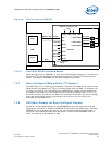
Figure 33 illustrates 42 IPMB buses emanating out of the two FPGAs, 21 buses from
each. Taken together, all buses are numbered 1 through 42. Buses numbered 1–21 are
IPMB-A buses implemented by FPGA1, and buses numbered 22–42 are IPMB-B buses
implemented by FPGA2. Though IPMB-A and IMPB-B bus pairs are intended to provide
redundancy, they could be used individually as well.
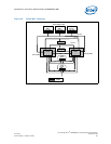
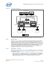
These buses can be configured to realize two basic IPMB bus topologies: radial and
shared. The actual usage model of these buses is ultimately up to the chassis designer.
Some possible usage scenarios have been listed in “Section 13.4.1, “Example
Configurations” on page 67.” The following sections provide graphical illustration of the
two basic bus topologies.
See Section 7.1.2, “CMM Data Connector” on page 36 for the signal names, pin
numbers, and connector information of the above-mentioned signals and buses. The 42
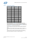
IPMB Buses are supported in all versions of firmware. The following table shows
mapping between the IPMB signal names and their corresponding physical bus number
as used by the CMM firmware.
Note: The physical bus numbers are 1-based (starting from 1), however in the configuration
files (required for third party chassis integration) a 0-based (starting from 0)
numbering scheme is used.
Each IPMB bus consists of two signals usually named SDA (data) and SCL (clock). The
table below only refers to the data(SDA) signal for simplicity. Also please note that all
the IPMB buses appear in redundant pairs with one set of signals named as A and the
other set of signals as B. Hence physical bus number 1 consists of the pair of signals
BP_N_SDA_[1]_A/ BP_N_SCL_[1]_A and it’s corresponding redundant bus with
physical bus number 22 consists of the pair of signals BP_N_SDA_[1]_B/
BP_N_SCL_[1]_B.
Figure 33. I/O Signals of the CMM
10 GPIOs
21 IPMB-B buses
FPGA1 FPGA2
21 IPMB-A buses
Dedicated I/IO signals
CPU
ADM 1026
SMBus
7 GPIOs
Analog Input 1
Analog Input 2
Analog Ground