


MPCMM0002 CMM—Mechanical Information
Intel NetStructure
®
MPCMM0002 Chassis Management Module
Hardware TPS July 2007
26 Order Number: 309247-004US
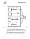
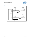
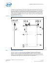
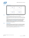
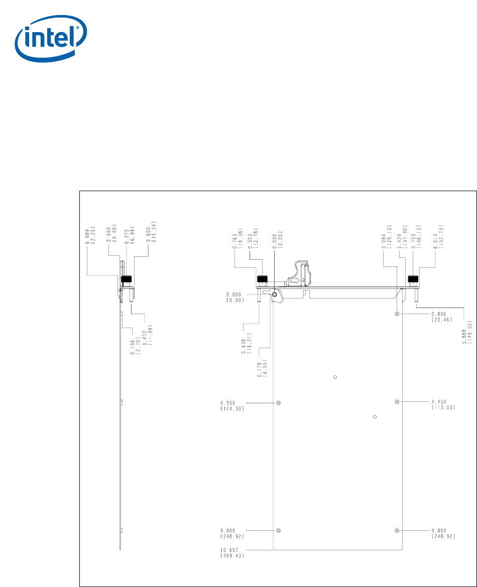
The gasket is on the secondary side of the backing plate and extends over the pitch
line, just as PICMG 3.0 boards extend their gasket over the pitch line. The outer face of
the backing plate is 0.15 mm (0.0059 inches) inside the nearest pitch line. Since the
gasket has a nominal compressed size of 1.53 mm (0.0602 inches) and a four-sigma
range of 0.99 mm (0.0390 inches) to 2.07 mm (0.0815 inches), the gasket must seal
on a surface that is between 0.84 mm (0.0331 inches) and 1.92 mm (0.0756 inches)
from the left side pitch line.
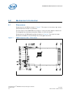
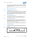
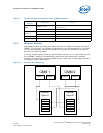
5.2 Front Panel Hardware
Table 18, “Telco Alarm Pinout” on page 49 shows two retention screws and two
alignment posts on the MPCMM0002 CMM faceplate. Like the hardware used with
PICMG* 3.0 boards, these items are M3 hardware. However, since the 15.24 mm (0.6
inches) pitch of the CMM does not allow sufficient room to put the retention screws and
alignment posts side by side, the alignment posts are offset slightly.
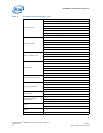
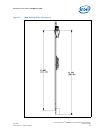
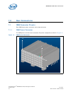
Figure 9. CMM Side View Dimensions