


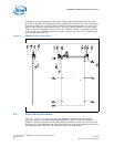
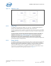
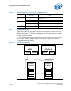
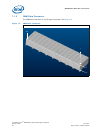
MPCMM0002 CMM—Rear Connections
Intel NetStructure
®
MPCMM0002 Chassis Management Module
Hardware TPS July 2007
34 Order Number: 309247-004US
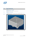
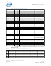
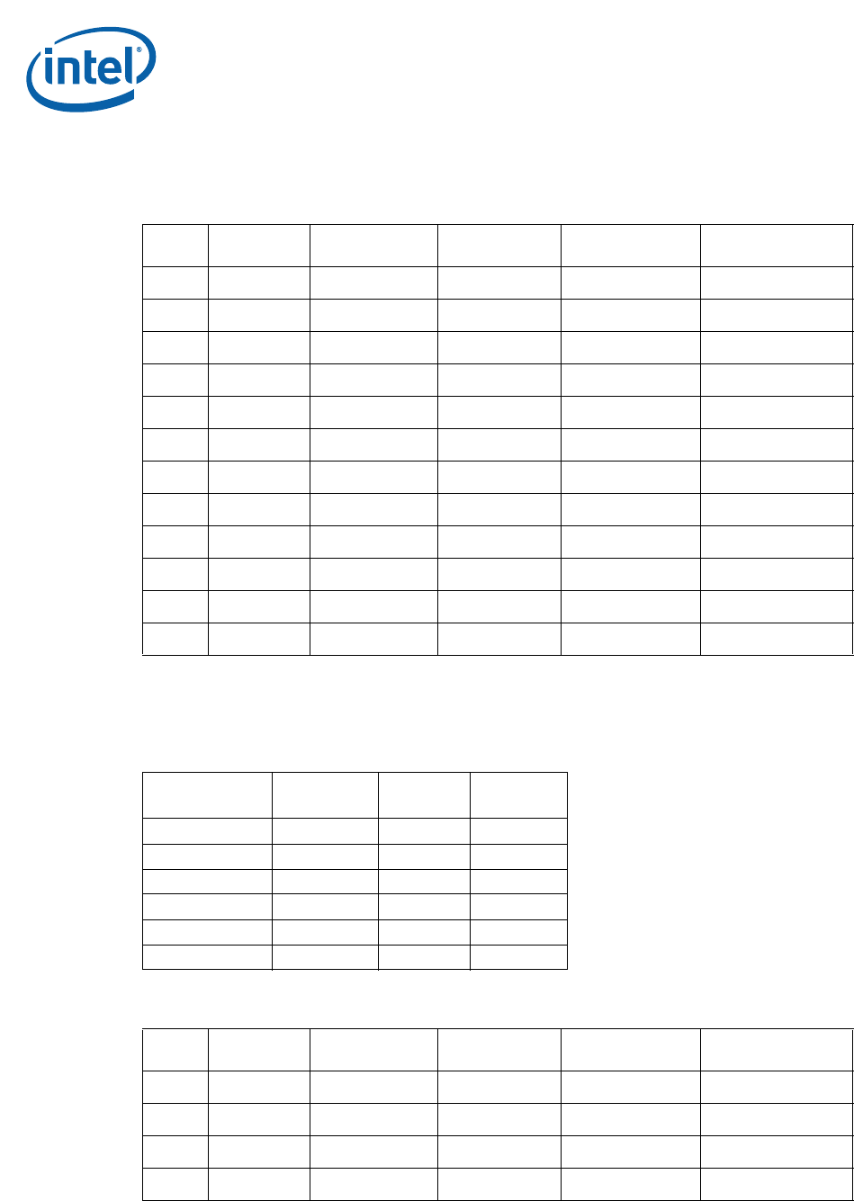
Table 7 labels the pins on the power connector at the intersection of each row (A-E) and
column (1-12).
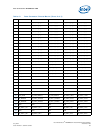
Table 8 shows the staging of the power connector pins. Table 9 and Table 10 (for the
receptacle and for the header) show the physical locations of the pins identified by pin
code.
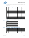
Table 7. Power Connector Pinouts Matrix
ED C B A
1 -48V_A -48V_A -48_A_RTN_MLBF
2 -48V_B -48V_B
3 -48_A_RTN -48_A_RTN -48_B_RTN_MLBF
4 -48_B_RTN -48_B_RTN
5 GND GND GND
6 PWRALRM_NO PWRALRM_COM
7 MNR_NO MJR_NO CRT_NO
8 MJR+ MJR-
9 MNR_COM MJR_COM CRT_COM
10 MNR+ MNR-
11 MNR_NC MJR_NC CRT_NC
12 SGND SGND
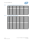
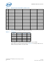
Table 8. Pin Staging
Order
Mating
Length
Tail
Length
Pin Code
First Mate 8 mm 4.3mm 19
Second Mate 7.25 mm 4.3mm 4
Third Mate 6.5 mm 4.3mm 3
Fourth Mate 5.75 mm 4.3mm 2
Last Mate 5 mm 4.3mm 1
Empty
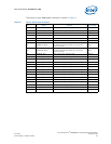
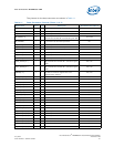
Table 9. Power Connector Receptacle Pin Placement (Sheet 1 of 2)
ED C B A
1 4 4 1
2 3 3
3 4 4 1
4 3 3