


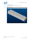
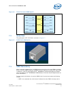
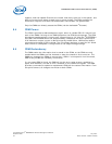
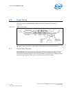
MPCMM0002 CMM—Rear Connections
Intel NetStructure
®
MPCMM0002 Chassis Management Module
Hardware TPS July 2007
40 Order Number: 309247-004US
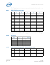
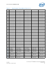
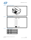
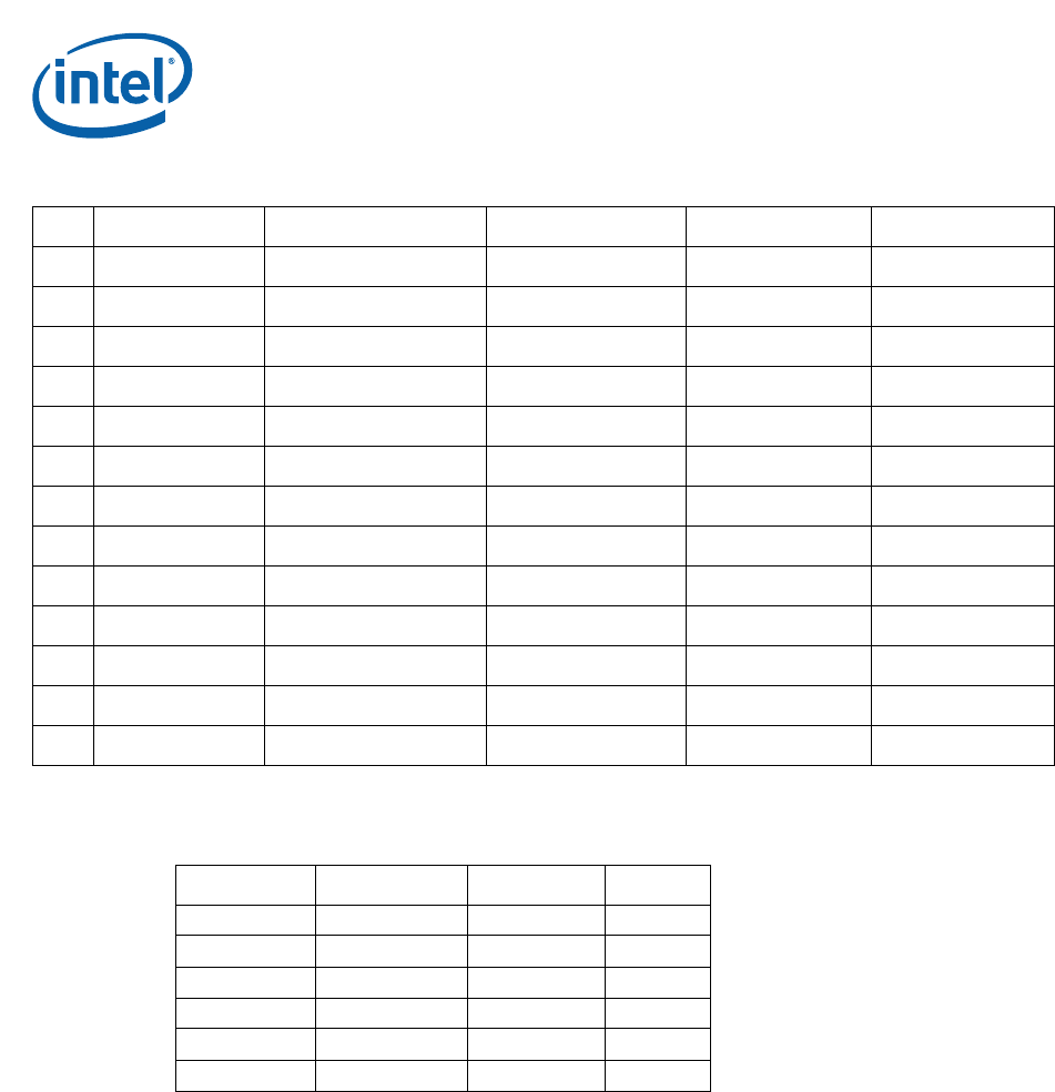
Table 13 shows the staging of the power connector pins.
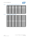
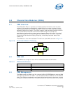
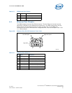
All the IPMB and I
2
C ports are wired in parallel between the two CMMs.
Some signals are cross-connected as shown in Figure 16. For example, NGO from one
CMM is connected to NGOI on the other CMM.
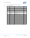
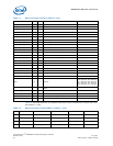
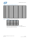
36 GND GND GND GND GND
37 RP_ENET2_TX1- RP_ENET2_TX1+ GND RP_ENET2_TX0- RP_ENET2_TX0+
38 GND GND GND GND GND
39 RP_ENET2_RX1- RP_ENET2_RX1+ GND RP_ENET2_RX0- RP_ENET2_RX0+
40 GND GND GND GND GND
41 BP_CMC_TX1- BP_CMC_TX1+ GND BP_CMC_TX0- BP_CMC_TX0+
42 GND GND GND GND GND
43 BP_CMC_RX1- BP_CMC_RX1+ GND BP_CMC_RX0- BP_CMC_RX0+
44 GND GND GND GND GND
45 BP_CMCX_TX1- BP_CMCX_TX1+ GND BP_CMCX_TX0- BP_CMCX_TX0+
46 GND GND GND GND GND
47 BP_CMCX_RX1- BP_CMCX_RX1+ GND BP_CMCX_RX0- BP_CMCX_RX0+
48 GND GND GND GND GND
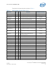
Table 12. Data Connector Pinouts Matrix (Sheet 3 of 3)
ED CBA
Table 13. Pin Staging
Order Mating Length Tail Length Pin Code
First Mate 8mm 4.3mm 19
Second Mate 7.25mm 4.3mm 4
Third Mate 6.5mm 4.3mm 3
Fourth Mate 5.75mm 4.3mm 2
Last Mate 5mm 4.3mm 1
Empty