


Intel NetStructure
®
MPCMM0002 Chassis Management Module
July 2007 Hardware TPS
Order Number: 309247-004US 53
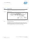
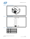
Front Panel—MPCMM0002 CMM
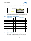
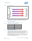
9.5.2 Health LED
Each CMM maintains a single health LED (®) to indicate the status of the CMM.
Possible states are described in Table 21.
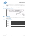
9.5.3 Hot Swap LED
Each CMM maintains a single blue Hot Swap LED (ÝÜ) to provide the status of the
CMM itself. Possible states are described in Table 22.
Note: Service personnel should be trained to wait for the solid blue LED before removing the
CMM from the system.
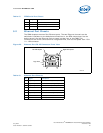
9.5.4 User-Definable LEDs
Each CMM provides four LEDs (A, B, C, D) that can be controlled via the operator or via
software automatically interacting with the CMM. Each LED can be off, green, yellow, or
red.
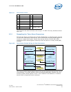
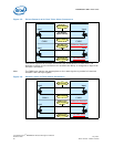
During the boot process, the user LEDs sequentially blink off to indicate boot progress.
The user LEDs will be off by the time the CMM software is fully loaded. Once the CMM is
up, the administrator can control the LED through standard interfaces or via
programmatic control. Methods to control these LEDs are described in the Intel
NetStructure
®
MPCMM0001 Chassis Management Module and Intel NetStructure
®
MPCMM0002 CMM Software Technical Product Specification.
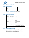
Table 21. CMM Health LED States
Color Description
Off No power to CMM
Solid Green Normal operation, power okay
Blinking Green CMM in standby mode
Solid Red/Amber Attention status (error condition) - CMM configures error color
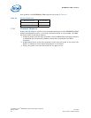
Table 22. CMM Hot Swap LED States
Color Description
Off In use
Long Blink Searching for CMM (900 ms on, 100 ms off)
Solid Blue Ready to remove
Short Blink Preparing for extraction (100ms on, 900 ms off)