


Intel NetStructure
®
MPCMM0002 Chassis Management Module
July 2007 Hardware TPS
Order Number: 309247-004US 27
Mechanical Information—MPCMM0002 CMM
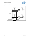
There is only one ejector on the CMM, but it matches the subrack interface geometry
defined in Section 2.2.7 of the PICMG 3.0 specification. Note, however, that the ejector
handle is 2 mm (0.0787 inches) thick, not the 2.5 mm (0.0984 inches) thickness that
many PICMG 3.0 boards use.
A switch on Component Side 2 of the PCB detects the opening and closing of the ejector
handle.
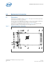
5.3 Rear Connector Placement
5.3.1 MPCMM0002 CMM Rear Connectors
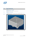
The CMM uses three connectors (for power, data, and a guide pin) that can mate with
either vertical (backplane) connectors or coplanar connectors. The power connector is
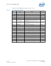
an FCI* 85719-107LF (or equivalent) connector. As shown in Table 14, “CMM Power
Connector” on page 32, the A1 pin on the connector is located at coordinates (2.37,
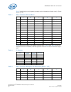
96.34). The data connector is an FCI 89095-102LF (or equivalent). Pin 1 on the data
connector is located at coordinates (13.7, 64.65). The guide pin connector is an FCI
73474-201 (or equivalent).
5.3.2 Coplanar Mating Connectors
In a coplanar mating arrangement, a FCI* HM1L54LDP000H6P connector with FCI*
72019-101 guide pin is mated to the data connector on the CMM, while a FCI*
HM1L52LDP493H6P (or equivalent) connector mates with the power connector.
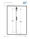
5.3.3 Vertical Mating Connectors
When a CMM board mates directly into a backplane, vertical mating connectors are
used. The data connector that mates to the CMM is a FCI* 89009-116 with FCI*
70295-001 guide pin and 73475-101 shroud, while the power connector is an FCI*
HM1W52ZPR493H6P (or equivalent). Since they are mounted on a backplane, the rear
of these two connectors must be in the same plane.
Example: If mounted horizontally with Component Side 1 up, the bottom row of holes
for the data connector is 1.775 mm (0.0699 inches) lower than the power connector.
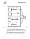
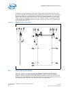
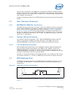
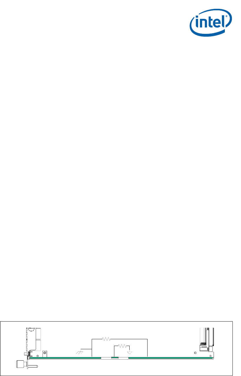
5.4 ESD Discharge Strip
The ESD strip along the bottom of the CMM follows the guidelines in Section 2.2.5 of
the PICMG* 3.0 specification. The electrical definition of the ESD discharge strip is
shown below.
Dimensions of the ESD strips are shown in Table 16, “Ethernet Port Pinouts” on
page 47.
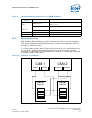
Figure 10. CMM ESD Strip Electrical Definition
10MΩ
10MΩ