


Intel NetStructure
®
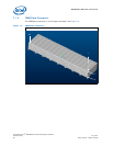
MPCMM0002 Chassis Management Module
July 2007 Hardware TPS
Order Number: 309247-004US 31
Backplane Considerations—MPCMM0002 CMM
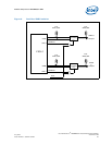
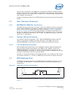
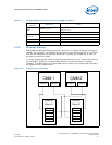
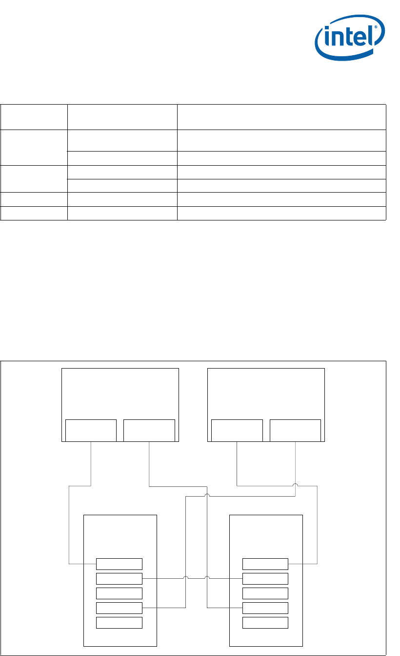
6.2.5 Ethernet Routing
Each CMM provides two Ethernet channels that can be routed to the base interface of
PICMG* 3.0 hub slots. The PICMG 3.0 specification only allocates space for one ShMC
slot, but the backplane can typically be set up to “poach” an unused slot in order to
provide a connectivity option.
A 14-slot chassis typically uses 14 base interface channels (13 for other slots plus one
for the ShMC). However, the specification defines 16 total channels for the base
interface. The second port from each CMM can be routed to an unused upper channel of
the opposite hub or fabric board.
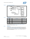
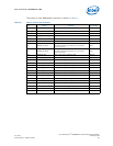
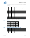
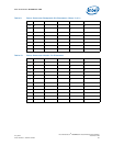
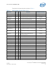
Table 5. Chassis Elements Directly Driven by CMM Hardware
Chassis
Element
Component Notes
CDM
EEPROM + others
50 mA @ 5 V max; typically uses series resistance to drop
voltage to 3.3.V.
LED Tricolor LEDs driven by CMM
Filter Tray
2 Thermistors NTC sensors, such as US Sensor USX2257
LED Red plus green LEDs driven by CMM
Power switch Dual pole switch Soft power switch to CMMs
LAN ports 2 LEDs each (4 total) Speed on one LED, Link and Activity on the other
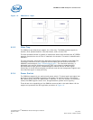
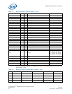
Figure 13. Ethernet Port Poaching
CMM 1
LAN A LAN B
CMM 2
LAN A LAN B
Ethernet
Fabric A
Port 0
Port 1
...
Port 14
Port 15
Ethernet
Fabric B
Port 0
Port 1
...
Port 14
Port 15