


MPCMM0002 CMM—Guidelines for Third Party Chassis Vendors
Intel NetStructure
®
MPCMM0002 Chassis Management Module
Hardware TPS July 2007
64 Order Number: 309247-004US
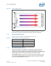
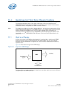
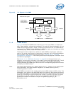
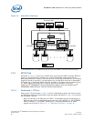
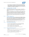
Among the 42 IPMB buses, two buses, 18 and 39 (signals BP_SH_SDA_A and
BP_SH_SDA_B respectively in Table 28), have a special feature. Each bus is wired to an
LTC4300 (IPMB bus isolator) part before making to the backplane. The IPMB bus
isolator allows detection of bus hangs. Intel highly recommends using these buses (in a
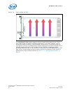
redundant mode) for chassis that use a shared bus topology. Figure 34 shows the radial
bus topology. Figure 35 shows the shared bus topology.
IPMB buses BP_RED_SDA_A/ BP_RED_SDA_B (physical bus number 19 and 40) are
reserved to be used as a dedicated redundant connection between two CMMs in the
chassis.
IPMB buses BP_CF_SDA_A/BP_CF_SDA_B (physical bus number 17 and 38) are
intended to be used as a dedicated redundant IPMB buses between CMMs and chassis
FRU.
IPMB buses BP_SP_SDA_A/BP_SP_SDA_B & BP_RP_SDA_A/BP_RP_SDA_B are
reserved for future use, however they can be configured by chassis vendors as any
general purpose IPMB buses in redundant or individual configuration.
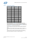
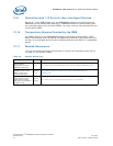
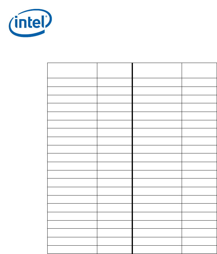
Table 28. Physical Bus Number Mapping
IPMB Signal
Physical
Bus Number
IPMB Signal
Physical
Bus Number
BP_N_SDA_[1]_A 1 BP_N_SDA_[1]_B 22
BP_N_SDA_[2]_A 2 BP_N_SDA_[2]_B 23
BP_N_SDA_[3]_A 3 BP_N_SDA_[3]_B 24
BP_N_SDA_[4]_A 4 BP_N_SDA_[4]_B 25
BP_N_SDA_[5]_A 5 BP_N_SDA_[5]_B 26
BP_N_SDA_[6]_A 6 BP_N_SDA_[6]_B 27
BP_N_SDA_[7]_A 7 BP_N_SDA_[7]_B 28
BP_N_SDA_[8]_A 8 BP_N_SDA_[8]_B 29
BP_N_SDA_[9]_A 9 BP_N_SDA_[9]_B 30
BP_N_SDA_[10]_A 10 BP_N_SDA_[10]_B 31
BP_N_SDA_[11]_A 11 BP_N_SDA_[11]_B 32
BP_N_SDA_[12]_A 12 BP_N_SDA_[12]_B 33
BP_N_SDA_[13]_A 13 BP_N_SDA_[13]_B 34
BP_N_SDA_[14]_A 14 BP_N_SDA_[14]_B 35
BP_N_SDA_[15]_A 15 BP_N_SDA_[5]_B 36
BP_N_SDA_[16]_A 16 BP_N_SDA_[16]_B 37
BP_CF_SDA_A 17 BP_CF_SDA_B 38
BP_SH_SDA_A 18 BP_SH_SDA_B 39
BP_RED_SDA_A 19 BP_RED_SDA_B 40
BP_RP_SDA_A 20 BP_RP_SDA_B 41
BP_SP_SDA_A 21 BP_SP_SDA_B 42