


Intel NetStructure
®
MPCMM0002 Chassis Management Module
July 2007 Hardware TPS
Order Number: 309247-004US 43
Chassis Data Modules (CDMs)—MPCMM0002 CMM
8.0 Chassis Data Modules (CDMs)
8.1 CDM Overview
The CDM (Shelf FRU) is a repository of chassis-specific information (such as serial
number of the chassis and backplane), capabilities of the system (number of slots,
maximum power per slot, whether dual star or mesh, etc.), and a few administrator-
definable configuration options. The latter category allows the administrator to define
more conservative limits than the maximum shelf ratings. For example, an
administrator could set the maximum power draw per feed to 30 A even if the shelf
itself were capable of handling 50 A per feed. CMMs use this information to provide
functions such as electronic keying (E-keying), controlling the power state of the
system, etc.
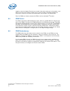
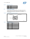
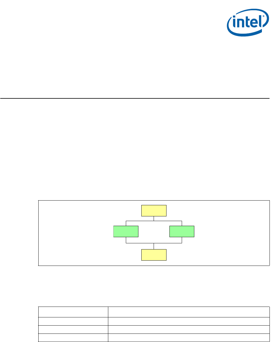
The CDMs sit on their own dedicated I
2
C links from each CMM, as shown in Figure 18.
8.2 CDM LED
The CMM drives a single tri-color LED to indicate the status of the module.
8.3 CDM Management
The CMM expects the CDM to act like a simple 24C64 I
2
C EEPROM device that the CMM
can read from and write to. CDM 1 is at I
2
C address 0xA2 and CDM 2 is at I
2
C address
0xA4. The CDMs are expected to store some limited configuration information, such as
the power-on state for each slot. The CDM contains the list of what slots are connected
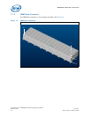
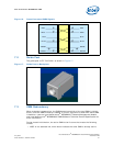
Figure 18. Chassis Data Module I
2
C Routing
CMM 1 CMM 2
CDM 1
CDM 2
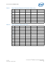
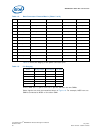
Table 14. CDM Health LED States
Color Description
Off No power to chassis
Solid Green Normal operation
Solid Red/Amber Attention status (error condition) - CMM configures error color