


Intel NetStructure
®
MPCMM0002 Chassis Management Module
July 2007 Hardware TPS
Order Number: 309247-004US 5
Contents—MPCMM0002 CMM
18.4 Instrucciones de Seguridad................................................................................. 87
18.5 Chinese Safety Warning ..................................................................................... 89
Figures
1 Top View of the Intel NetStructure
®
MPCMM0002 CMM ................................................. 13
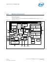
2 CMM Block Diagram ................................................................................................. 15
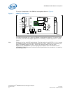
3 CMM Top View Layout...............................................................................................16
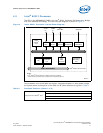
4 Intel® 80321 Processor Internal Block Diagram ........................................................... 17
5 IPMB Dual Star Isolation ........................................................................................... 22
6 Dual Bus IPMB Isolation............................................................................................ 23
7 CMM Component Side 1 Dimensions ........................................................................... 24
8 CMM Backing Plate Dimensions ..................................................................................25
9 CMM Side View Dimensions ....................................................................................... 26
10 CMM ESD Strip Electrical Definition............................................................................. 27
11 Power System Block Diagram ....................................................................................29
12 CDM Power Input..................................................................................................... 30
13 Ethernet Port Poaching ............................................................................................. 31
14 CMM Power Connector .............................................................................................. 32
15 CMM Data Connector................................................................................................ 36
16 Cross-Connected CMM Signals ................................................................................... 41
17 Guide Post to Backplane ...........................................................................................41
18 Chassis Data Module I2C Routing............................................................................... 43
19 CMM Front Panel...................................................................................................... 45
20 Serial Port RJ-45 Connector.......................................................................................46
21 Serial Port RJ-45 Cabling........................................................................................... 46
22 Ethernet Port RJ-45 Connector Front View ................................................................... 47
23 DB-15 Telco Alarm Connector.................................................................................... 48
24 Telco Alarm Contact Wiring for Dual Connectors........................................................... 49
25 Failure Scenario with Dual Telco Alarm Connectors ....................................................... 50
26 Parallel Inputs to Telco Alarm Connectors.................................................................... 50
27 Cascaded Telco Alarm Cables..................................................................................... 51
28 CMM Front Panel with Labels ..................................................................................... 52
29 CMM Heat Sink ........................................................................................................ 55
30 Side-to-Side Air Flow................................................................................................ 56
31 Front-to-Back Air Flow.............................................................................................. 57
32 High Level CMM Design............................................................................................. 62
33 I/O Signals of the CMM .............................................................................................63
34 Radial Bus Topology .................................................................................................65
35 Shared Bus Topology................................................................................................ 66
36 FRU That Uses the ADM1026 ..................................................................................... 69
Tables
1 Acronyms and Terms................................................................................................ 10
2 Processor Features...................................................................................................17
3 FPGA Features......................................................................................................... 20
4 Voltage Usage ......................................................................................................... 29
5 Chassis Elements Directly Driven by CMM Hardware ..................................................... 31
6 Power Connector Pinouts........................................................................................... 33
7 Power Connector Pinouts Matrix ................................................................................. 34
8 Pin Staging ............................................................................................................. 34
9 Power Connector Receptacle Pin Placement ................................................................. 34
10 Power Connector Header Pin Placement ...................................................................... 35
11 Data Connector Pinouts ............................................................................................ 37
12 Data Connector Pinouts Matrix................................................................................... 38
13 Pin Staging ............................................................................................................. 40