


Intel NetStructure
®
MPCMM0002 Chassis Management Module
July 2007 Hardware TPS
Order Number: 309247-004US 3
Contents—MPCMM0002 CMM
Contents
1.0 Document Organization.............................................................................................8
1.1 Acronyms and Terms......................................................................................... 10
2.0 Introduction............................................................................................................ 11
2.1 Architecture Specification ................................................................................... 11
2.2 User Documentation .......................................................................................... 11
2.3 Product Definition.............................................................................................. 11
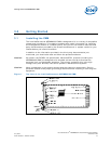
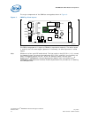
3.0 Getting Started........................................................................................................ 13
3.1 Installing the CMM.............................................................................................13
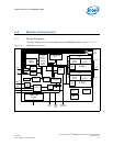
4.0 Module Components ................................................................................................ 15
4.1 Block Diagram .................................................................................................. 15
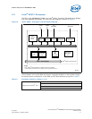
4.2 Intel® 80321 Processor ..................................................................................... 17
4.3 Memory ........................................................................................................... 19
4.4 Ethernet .......................................................................................................... 19
4.5 Serial Port UARTs.............................................................................................. 19
4.6 FPGA ............................................................................................................... 20
4.7 Redundancy and Hot Swap CPLD......................................................................... 20
4.8 Watchdog Timer................................................................................................ 20
4.9 Real-Time Clock................................................................................................ 20
4.10 ADM1026 Controller ..........................................................................................21
4.11 Hot Swap Controller........................................................................................... 21
4.12 Ride-Through Support........................................................................................ 21
4.13 IPMB Isolation Logic ..........................................................................................21
5.0 Mechanical Information........................................................................................... 24
5.1 Dimensions ...................................................................................................... 24
5.2 Front Panel Hardware ........................................................................................ 26
5.3 Rear Connector Placement..................................................................................27
5.4 ESD Discharge Strip ..........................................................................................27
6.0 Backplane Considerations........................................................................................28
6.1 IPMB Routing.................................................................................................... 28
6.2 CMM Power ...................................................................................................... 28
7.0 Rear Connections .................................................................................................... 32
7.1 CMM Connector Pinouts...................................................................................... 32
7.2 Guide Post........................................................................................................ 41
7.3 CMM Redundancy.............................................................................................. 41
8.0 Chassis Data Modules (CDMs).................................................................................. 43
8.1 CDM Overview .................................................................................................. 43
8.2 CDM LED.......................................................................................................... 43
8.3 CDM Management ............................................................................................. 43
8.4 CDM Power....................................................................................................... 44
8.5 CDM Redundancy ..............................................................................................44
9.0 Front Panel.............................................................................................................. 45
9.1 Serial Port Pinouts.............................................................................................45
9.2 Ethernet Port Pinouts.........................................................................................47
9.3 Telco Alarm Connector....................................................................................... 48
9.4 Alarm Quiet Switch............................................................................................ 51
9.5 LEDs................................................................................................................52
10.0 Grounding Considerations ....................................................................................... 54