Working page only. Do not distribute.
1
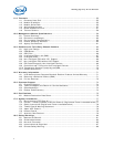
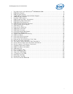
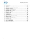
1 Acronyms and Terms ................................................................................................10
2 Processor Features ...................................................................................................17
3 FPGA Features .........................................................................................................20
4 Voltage Usage..........................................................................................................29
5 Chassis Elements Directly Driven by CMM Hardware......................................................31
6 Power Connector Pinouts ...........................................................................................33
7 Power Connector Pinouts Matrix .................................................................................34
8 Pin Staging..............................................................................................................34
9 Power Connector Receptacle Pin Placement..................................................................34
10 Power Connector Header Pin Placement.......................................................................35
11 Data Connector Pinouts.............................................................................................37
12 Data Connector Pinouts Matrix ...................................................................................38
13 Pin Staging..............................................................................................................40
14 CDM Health LED States .............................................................................................43
15 RTM Serial Port Pinout...............................................................................................46
16 Ethernet Port Pinouts ................................................................................................47
17 Ethernet Port LED States ...........................................................................................48
18 Telco Alarm Pinout....................................................................................................49
19 Ganged Telco Alarm Cable Pinouts with Cabling ............................................................51
20 CDM Health LED States .............................................................................................52
21 CMM Health LED States.............................................................................................53
22 CMM Hot Swap LED States.........................................................................................53
23 Typical Airflow and Cooling Requirements ....................................................................57
24 Airflow Guidelines.....................................................................................................58
25 Dimensions and Weight.............................................................................................60
26 Environmental Characteristics ....................................................................................60
27 Reliability Estimate Data............................................................................................61
28 Physical Bus Number Mapping....................................................................................64
29 Related Documents...................................................................................................70
30 MPCMM0002 Product Code Summary ..........................................................................74


