


MPCMM0002 CMM—Module Components
Intel NetStructure
®
MPCMM0002 Chassis Management Module
Hardware TPS July 2007
20 Order Number: 309247-004US
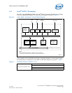
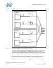
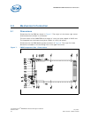
4.6 FPGA
The MPCMM0002 CMM has two redundant field-programmable gate arrays (FPGAs) on
board. These two Xilinx* Spartan* II XC2S200 FPGAs have identical internal design,
but different addresses. A brief summary of the FPGA functions is shown in Table 3.
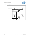
4.7 Redundancy and Hot Swap CPLD
A Xilinx XC95144XL CPLD is used on the CMM to control the redundancy failover logic,
Hot Swap logic, FPGA control, and address decode for simple devices on the CMM. This
CPLD also contains the PCI arbitration circuitry for the 80321 processor and the
Ethernet controllers.
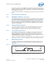
4.8 Watchdog Timer
A Maxim* MAX6374KA-T watchdog timer is used to protect against CPU lockups. The
CMM firmware strobes the watchdog periodically; if the CPU fails to strobe the
watchdog within a given time interval, the watchdog sends a signal to the CPLD that
forces the CPU to reset. This allows the processor to automatically recover to a known
good state in the case of lockup.
Note: If the watchdog timer fires, the IPMB signals are not affected by the CPU timer reset.
The other CMM automatically takes over and manages the chassis.
4.9 Real-Time Clock
The CMM time-stamps certain events as they occur within the system, particularly
entries into the System Event Log (SEL). A Dallas Semiconductor* DS1307 real-time
clock provides this capability.
To avoid losing the current time, the CMM provides independent power to the DS1307
with an on-board battery (size CR2032). The battery provides approximately five years
of run time for the clock in case of a power failure or if the CMM is removed from a
chassis.
Batteries have limited shelf lives. After many years in storage, a battery may not be
able to hold a charge. To supplement the battery, a super capacitor (SCap) is also
provided on the CMM; this provides a mechanism to get up to two hours of backup
power for the clock in case of a power failure. Though the SCap will not hold a charge
for even a full day, the ability to power the clock circuit during a power failure even
after years in storage is a reliability feature of the CMM.
The battery and SCap are both diode-OR’d to ensure that either one can supply the
power for the clock without being affected by the other backup power source.
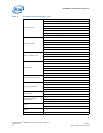
Table 3. FPGA Features
Signal Description
IPMB
compatible
buses
IPMI 1.5-compliant buses, pulled up to 3.3 V and operating at 100 kHz
20 IPMB ports per FPGA (40 total): 32 IPMBs for dual star routing to up to 16
AdvancedTCA* slots, 2 shared buses for PEMs and fan trays, 2 buses for communication
between CMMs, and 4 spare IPMBs for future expansion
One I
2
C port per FPGA (2 total) for communication to CDMs
Bus 50nS basic memory bus with data, address, chip select, output enable, and write enable
Interrupt
Router
The FPGA is responsible for identifying and routing interrupt requests from multiple sources
on the CMM, including the following: internal IPMB engine, other FPGA, both UARTs, the
ADM1026 controller, the CPLD, and both LAN controllers