


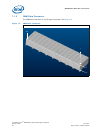
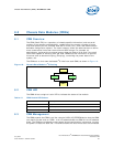
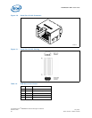

MPCMM0002 CMM—Chassis Data Modules (CDMs)
Intel NetStructure
®
MPCMM0002 Chassis Management Module
Hardware TPS July 2007
44 Order Number: 309247-004US
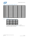
together, how the Update Channels are routed, how many slots are in the system, and
what is the maximum power to each slot or group of slots. The CDM provides the
information required of a shelf FRU as defined in the PICMG* 3.0 specification.
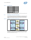
Only the CMMs can directly access the CDMs (via the dedicated I
2
C buses).
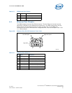
8.4 CDM Power
The CDM is provided a dedicated power signal, which is a diode-OR’d 5 V output from
each of the CMMs. As long as one CMM has power, the CDM should operate. The CDM
should use a series resistor to lower the 5 V power input to 3.3 V for the I
2
C EEPROM in
the CDM. I2C EEPROM should not be powered by 5V because I2C bus is pulled up at
3.3V. Maximum output current is 40mA limited by the 69.8ohm 1/8W series resistor
connected at the end of OR-ing diode. The 5V voltage regulator is rated for 3A. 40mA
load current for CDM power is insignificant to the output voltage change.
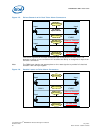
8.5 CDM Redundancy
The CMMs cache the information that is stored in the CDMs, so the CDMs are only
needed when the CMMs are first inserted or when the chassis is first turned on. The
CMMs can manage two CDMs to ensure that, if CDM 1 is corrupted or non-functional,
CDM 2 can provide the necessary information.
If a corrupted CDM is found, the CMM will log the error, raise an error condition to
upper-level software, and set an error condition on the CDM’s LED signals. The CMM
provides a command to update a replacement CDM with the cached information. From
this point forward, all changes are written to both CDMs.