


MPCMM0002 CMM—Front Panel
Intel NetStructure
®
MPCMM0002 Chassis Management Module
Hardware TPS July 2007
48 Order Number: 309247-004US
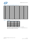
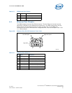
There are two LEDs for each Ethernet port.
.
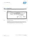
9.3 Telco Alarm Connector
Many telecom facilities have existing alarm infrastructure. When an error condition
occurs, the alarm system activates an audible alarm, flashes lights to help technicians
locate the source of the alarm, and possibly interacts with a computer system that is
monitoring the facility. Error conditions are typically classified as minor, major, or
critical errors, and an LED identifies the current alarm state.
The telco alarm system consists of a distinct dry contact relay that corresponds to each
alarm state. These are open or closed depending on the state and are entirely under
software control (except power). The default is the no alarm state. The normally open
[NO], normally closed [NC], and common [COM] relay contacts are provided to the DB-
15 connector in line with existing industry practice. There are also reset inputs to clear
the minor and major alarm state.
Note: There is no reset for the critical state.
There is an additional set of contacts (common [COM] plus normally open [NO]) that is
used to indicate a power system failure. There is no normally closed [NC] contact for
this relay nor is there a reset for clearing it.
The telco alarm contacts on the MPCMM0002 CMM comply with the alarm connector
requirements outlined in Section 2.7.7 of the PICMG* 3.0 specification.
Caution: The RTM connections for the telco alarm connections are wired parallel to the
connections on the CMM faceplate. Do not connect cables to both the DB-15 connector
on the CMM and the corresponding RTM alarm connector at the same time.
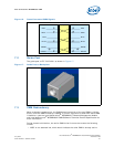
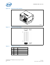
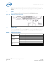
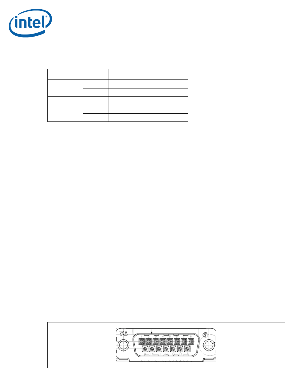
The DB-15 is a standard DB-15 connector, such as a Tyco* V23529-S1101-C215
connector.
The pinout for the DB-15 is shown below.
Table 17. Ethernet Port LED States
LED (Color) Status Description
Yellow LED
Off 10 Mbps Connection
On 100 Mbps Connection
Green LED
Off No Link
Blinking Transmission Activity
Solid On Link established, but no activity
Figure 23. DB-15 Telco Alarm Connector