


Intel NetStructure
®
MPCMM0002 Chassis Management Module
July 2007 Hardware TPS
Order Number: 309247-004US 29
Backplane Considerations—MPCMM0002 CMM
The CMM supports an input voltage range of –34 VDC to –72 VDC. However, the 5 ms
ride-through capability (see Section 4.12, “Ride-Through Support” on page 21)
assumes a prior minimum voltage of –43 VDC.
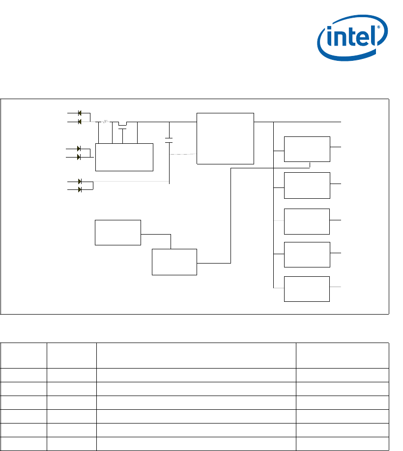
6.2.2 CDM Power
The CMM provides a few powered outputs that chassis designers can use as they see
fit. The chassis data modules (sometimes called shelf FRUs) are described in more
detail in Section 8.0, “Chassis Data Modules (CDMs)” on page 43. Each CMM provides a
diode-OR’d 5 V output at 50 mA maximum current to the CDMs. Chassis designers can
use this 5 V output to power simple EEPROMs in a CDM. The CMMs can both drive a
tricolor LED on the CDM as well.
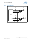
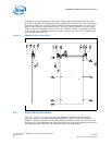
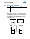
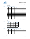
Figure 11. Power System Block Diagram
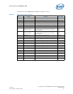
Table 4. Voltage Usage
Voltage
Max
Current
Where Used Monitored By
12 V 0.3 A Op Amp and IPMB isolation circuit ADM1026
5 V 1 A Misc components that cannot use 3.3 V ADM1026
3.3 V 4 A Most logic ADM1026
2.5 V 5 A Memory interface ADM1026
1.3 V 3 A IOP321 core ADM1026
1.25 V 1 A DDR Termination ADM1026
Hotswap
C ontroller
Filter
Cap
-48V
3.3V
5V
12V
LT1371
ADM1026
Power
Enable
(MLBF)
PG5
PG33
CPLD
2.5V
1.25V
Discrete
Linear
Regulator
-48V Return
-48V to
3.3V
Power
Brick
TPS54610
1.3V
TPS54610
LT1930