


MPCMM0002 CMM—Backplane Considerations
Intel NetStructure
®
MPCMM0002 Chassis Management Module
Hardware TPS July 2007
28 Order Number: 309247-004US
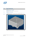
6.0 Backplane Considerations
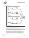
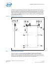
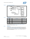
6.1 IPMB Routing
The Intel NetStructure
®
MPCMM0002 CMM is designed to support a hybrid dual IPMB
star topology.
The CMMs can support up to 16 slots, the maximum number of boards in a PICMG* 3.0
chassis. Each board in the subrack has two dedicated IPMBs going to it. Each IPMB is
arranged in a ‘Y’ pattern: the connection from the board is split to two legs, one going
to each CMM. Each CMM is present on both buses to each board. In addition, there are
two shared IPMB buses routed between the CMMs for private, dedicated IPMB traffic
between the two CMMs. While the CMMs theoretically can talk between themselves
over any of 30+ IPMBs, the private IPMB traffic between CMMs is normally over these
two inter-CMM links.
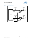
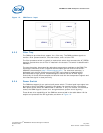
Note: A shared dual IPMB bus is used for chassis elements such as PEMs and one or more fan
trays. This shared dual bus allows the CMM to support varying numbers of PEMs, fan
trays, and other intelligent chassis elements.
In compliance with the PICMG 3.0 specification, the shared bus IPMB signals have an
isolating buffer device (LTC4300) to ensure proper bus isolation in a shared bus
environment. The radial (star) IPMB connections to each node are not required to have
this same isolation circuitry since each node is effectively isolated already by the star
topology.
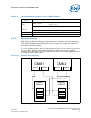
6.2 CMM Power
6.2.1 DC Power Input
Each CMM receives dual -48 VDC power feeds on its power connector. Since the
maximum power draw is 28 W, the maximum power draw from each CMM is less than 1
A. The typical power draw for each CMM is 17 W. Most of the power is derived from the
3.3 V converter.