3-13
Nº40 Media Console Rear Panel Operation
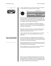
AES/EBU and S/PDIF
on BNC Digital Inputs
As shipped from the factory, slot 5 is normally used for a digital
input card that includes two AES/EBU connections on XLR and one
S/PDIF connection on a BNC connector.
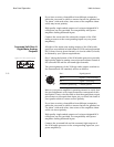
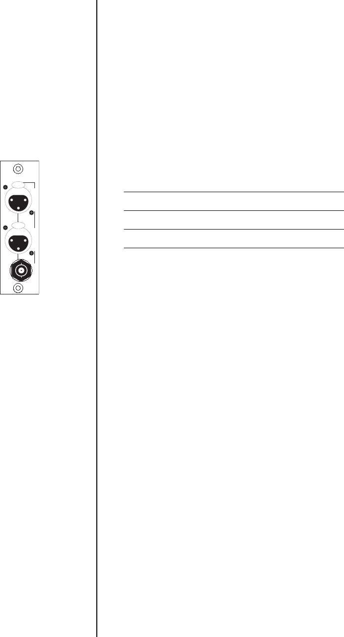
The top two connectors (connectors 1 & 2) accept digital audio in
the professional 110Ω AES/EBU digital interface standard (via a
cable equipped with XLR-type connectors) from a digital satellite
receiver, compact disc, laserdisc, DVD or other digital source
component. Connect the AES/EBU digital output of your source
component to the AES/EBU input of the Nº40 using a high quality
110Ω AES/EBU cable.
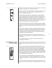
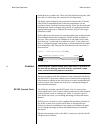
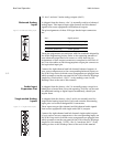
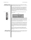
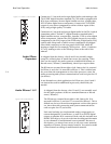
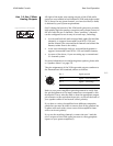
Figure 3-18: AES/EBU & SPDIF inputs. The pin assignments of these AES/EBU XLR-type female input
connectors are:
These pin assignments are consistent with the standards adopted by
the Audio Engineering Society and the European Broadcast Union.
Refer to the operating manuals of your digital sources to verify that
the pin assignments of their output connectors correspond to the
Nº40 audio processor. If not, wire the cables so that the appropriate
output pin connects to the equivalent input pin.
The BNC connector on this card (connector 3) accepts digital audio
conforming to the 75Ω S/PDIF digital interface standard (via 75Ω
cables equipped with BNC-type connectors) from a digital satellite
receiver, compact disc, DVD or other digital source component.
Connect the 75Ω S/PDIF output of your source component to either
of these inputs of the Nº40 audio processor, using a high quality
75Ω cable.
Keep track of which source components are plugged into which
connectors on the rear panel of the Nº40, either by keeping a
simple list or by making a note on the Hookup Chart at the end of
this manual.
SPDIF on RCA and
EIA-J Digital Inputs
As shipped from the factory, slots 6 and 7 are normally used for two
digital input cards that include three S/PDIF connections on RCA
and two EIA-J optical connections each.
2 aes/ebu
3 spdif1 aes/ebu
digital inputs
PUSH
21
3
PUSH
21
3
Pin 1 Shield
Pin 2 Digital + (non-inverting)
Pin 3 Digital – (inverting)
Connector ground lug chassis ground


