3-16
Rear Panel Operation Mark Levinson
If additional DSP power should become necessary at some point
in the future to perform yet more audio processing tasks, it is
possible to add an additional four SHARCs to this card.
However, this is not necessary at this time as the Nº40 already
has a tremendous amount of DSP power.
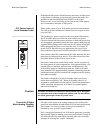
IEC Power Input &
Serial Number Label
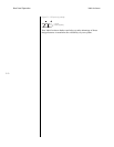
Please make a note of your Nº40 audio processor serial number .
You will need this information should you ever require service
on your Nº40.
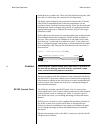
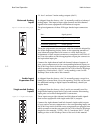
Figure 3-22: Label & power plug. The latching AC power switch on the front panel disconnects
the Nº40 audio processor from the wall outlet’s AC power.
Check to ensure that the power switches on both the processors
are disengaged (protruding from the front panel), then plug the
supplied three-prong power cords into the AC mains receptacles
before plugging the power cord into the wall. (If a longer AC
power cord is required for your application, be sure to use a
three-conductor power cord which conforms to IEC standards.)
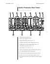
Also connect the Nº40 communications cable between the two
processors as indicated in 8, above. This cable allows the video
and audio halves of the Nº40 to work as one.
Once the connections are all firmly made, switch on power at
the front panels of both components. After approximately a 30-
second delay to initialize and run some self-diagnostics, the
Nº40 will be ready for initial setup and use. Please wait until
their standby LEDs begin blinking together, indicating that the
initialization and self-test routines are complete and the system
has entered standby.
The Nº40 is designed to be left in Standby when not in use,
rather than completely “off.” Being in Standby allows it to
respond to commands from the remote control and maintains a
stable operating temperature at all times for optimal perfor-
mance and longevity.
Caution The Mark Levinson Nº40 has been safety-tested and is designed
for operation with a three-conductor power cord. Do not defeat
the earth ground pin of the AC power cord.
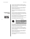
Front Left & Right
Main Analog Outputs
(slot A)
All eight of the main zone analog outputs of the Nº40 audio
processor are available in both balanced (XLR) and single-ended
(RCA) form. You can use either on any given channel, as
dictated by your system’s requirements.
Slot A (along the bottom of the Nº40 audio processor) provides
high quality digital to analog conversion and volume control of
the front left and the front right channels (the ones normally
thought of as being the “stereo” channels).
S/N
Made in the U.S.A.
MARK LEVINSON
MEDIA CONSOLE Nº40
AUDIO PROCESSOR
~
ac mains


