3-15
Nº40 Media Console Rear Panel Operation
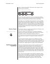
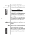
Connect either (or both) of the audio outputs to your intended
remote zone system or audio recorder, according to your system
design.These audio outputs can easily drive extremely long
lengths of high quality cable; however, as with any audio
signal, long cable runs really require excellent quality cable to
avoid signal deterioration. Please consult with your dealer on
the best choice of cable to suit your system design.
From the front panel, you can select the zone you wish to
change using the zone knob, and then route any defined input
to both the audio outputs associated with the selected RZone
using the input select knob.
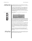
If you need to control a particular zone from a remote location,
simply use IR “repeaters” to direct appropriate infrared
commands to the IR input on that RZone card, in the video
processor. Any commands received at an IR input will be inter-
preted as being intended for that particular RZone.
Keep track of how these outputs are used, either by keeping a
simple list or by making a note on the Hookup Chart at the end
of this manual.
See“Using the RZones” on page 6-1 for more information on
configuring your RZones.
Audio Processing and
System
Communications
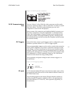
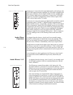
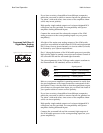
Slot 12 of the Nº40 audio processor is reserved for two purposes:
• The card in Slot 12 handles the communications with the
Nº40 video processor, via the dedicated Nº40 communica-
tion port.
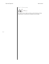
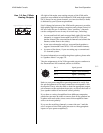
Figure 3-21: Control card. • The card also includes an auxiliary communication port
that is reserved for future use. (You can safely ignore it for
now.)
• This card also handles all the digital signal processing for
the audio signals, using four SHARC 32-bit DSP chips to
perform Dolby Digital, DTS, and MPEG decoding; electronic
crossover and bass management functions; THX and similar
post-processes; matrix decoding of 2-channel signals.
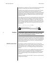
The two “halves” of the Nº40 (the video processor and the
audio processor) need to be able to “talk to each other.” The
Nº40 communications port on each component is reserved for
this purpose.
Please connect this connector and similarly-labelled connector
on the other component, using the supplied RJ-11 communica-
tions cable. After having done so, power up both units and
please wait until their standby LEDs begin blinking together,
indicating that the initialization and self-test routines are
complete and the system has entered standby.
control
Nº40
comm.
aux comm.


