3-17
Nº40 Media Console Rear Panel Operation
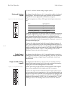
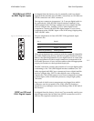
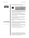
Figure 3-23: Front LR analog
outputs.
The pin assignments of the XLR-type male outputs conform to
the international AES standard, and are as follows:
Refer to your power amplifier operating manual to verify that
the pin assignments of its input connectors correspond to this
description. If not, wire the cable so that the appropriate output
pin connects to the equivalent input pin, or reverse the leads of
your speaker cables to restore correct polarity.
If you have a variety of amplifiers from different companies,
particular care must be taken to ensure that all the speakers are
“in phase” with each other, since some of the amplifiers them-
selves may invert polarity.
High quality single-ended outputs on Levinson-designed RCA
connectors are also provided, for compatibility with power
amplifiers lacking balanced inputs.
Connect the front left and the front right outputs of the Nº40
audio processor to the corresponding inputs on your power
amplifier(s).
Center and Subwoofer
Main Analog Outputs
All eight of the main zone analog outputs of the Nº40 audio
processor are available in both balanced (XLR) and single-ended
(RCA) form. On any given channel, you can use either (or both)
as dictated by your system requirements.
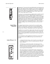
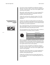
Figure 3-24: Center/Sub outputs.: Slot B (along the bottom of the Nº40 audio processor) provides
high quality digital to analog conversion and volume control of
the center and the subwoofer channels.
The pin assignments of the XLR-type male outputs conform to
the international AES standard, and are as follows:
Refer to your power amplifier operating manual to verify that
the pin assignments of its input connectors correspond to this
description. If not, wire the cable so that the appropriate output
pin connects to the equivalent input pin, or reverse the leads of
your speaker cables to restore correct polarity.
right
left
analog outputs
slot A
Pin 1 Signal ground
Pin 2 Signal + (non-inverting)
Pin 3 Signal – (inverting)
Connector ground lug Chassis ground


