


VOICE MODE
122
CONTROLLER
The Controller parameters function screen lets you perform
operations which determine the status of the various control-
lers, including pitch bend and modulation wheels, sustain,
aftertouch, foot control and MIDI control.
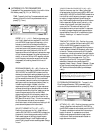
● ACCESSING CONTROLLER PARAMETERS
To access the Controller parameter function, from within
Voice Edit Mode, press [F8] ( Ctrl ) or TRACK [16].
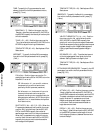
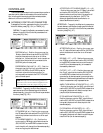
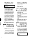
SUSTAIN - To specify the Sustain parameters for each
element, from within the Controller parameters func-
tion, press [F2] ( Sus ).
SUSTAIN (off, on) - Position the cursor over the
Sustain status field and use the JOG or INC/DEC
to switch the sustain controller on or off. When
switched on , the foot switch will control sustain on
and off when the foot switch is connected to the
SUSTAIN jack on the rear panel.
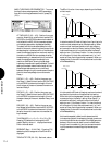
EXPRESSION LOW LIMIT (0 ~ 127) - Position
the cursor over the ExpLLmt value field and use
the JOG, INC/DEC or the KEYPAD to set the
minimum volume for the foot controller (i.e.,
volume pedal) connected to the FOOT VOLUME
jack on the rear panel.
NOTE: The Expression Low Limit Setting will have no
effect unless you set the Foot Volume assignment to 011
(see Utility Mode, Controllers, Expression, page 147).
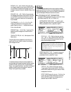
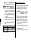
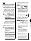
PITCH BEND - To specify the Pitch Bend status for
each element and Pitch Bend settings which affect all
elements equally, from within the Controller parameters
function, press [F3] ( PB ).
PITCH BEND (off, on) - Position the cursor over
the PB status field and use the JOG or INC/DEC to
switch the pitch bend controller on or off for each
element.
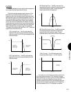
PITCH BEND RANGE (0 ~ 12) - Position the
cursor over the PB Range value field and use the
JOG, INC/DEC or the KEYPAD to determine how
much the pitch will change (for all elements equally)
when moving the pitch bend wheel.
AFTERTOUCH PITCH BEND RANGE (-12 ~ +12)
- Position the cursor over the AT P.Bend value field
and use the JOG, INC/DEC or the KEYPAD to
determine how much the pitch will change (for all
elements equally) by aftertouch. (NOTE: The
aftertouch parameter must be switched to on
status. See Aftertouch, below.)
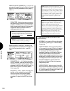
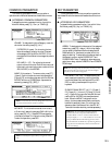
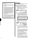
AFTERTOUCH - To specify the Aftertouch parameters
for each element and Aftertouch settings which affect all
elements equally, from within the Controller parameters
function, press [F4] ( AT ).
AFTERTOUCH (off, on) - Position the cursor over
the AT status field and use the JOG or INC/DEC to
switch the aftertouch controller on or off for each
element.
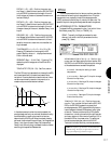
EG BIAS (-127 ~ +127) - Position the cursor over
the EG Bias value field and use the JOG, INC/DEC
or the KEYPAD to determine how much the ampli-
tude EG (for all elements equally) is increased or
decreased by aftertouch.
CUTOFF (-127 ~ +127) - Position the cursor over
the Cutoff value field and use the JOG, INC/DEC
or the KEYPAD to determine how the cutoff fre-
quencies (for all elements equally) are controlled by
aftertouch. Positive settings cause the cutoff frequen-
cies to increase when a key is pressed harder.
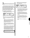
AMPLITUDE MODULATION DEPTH (0 ~ 127)
- Position the cursor over the AMD value field and
use the JOG, INC/DEC or the KEYPAD to determine
how greatly aftertouch will affect the output level
(amplitude) of all elements equally.
PITCH MODULATION DEPTH (0 ~ 127) -
Position the cursor over the PMD value field and
use the JOG, INC/DEC or the KEYPAD to determine
how greatly aftertouch will affect the pitch of all
elements equally.
FILTER MODULATION DEPTH (0 ~ 127) -
Position the cursor over the FMD value field and
use the JOG, INC/DEC or the KEYPAD to determine
how greatly aftertouch will affect the cutoff frequen-
cies of the filter (for all elements equally).