


126
Voice Mode
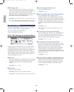
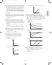
■ HPF K.Flw (High Pass Filter KeyFollow)
Sets the KeyFollow for the High Pass Filter cutoff
frequency. The High Pass Filter KeyFollow function
controls the change in the cutoff frequency by the
notes played on the keyboard. When set to a positive
value, the higher the note played on the keyboard,
the higher the cutoff frequency becomes. When a
negative value is set, the lower the note played, the
higher the cutoff frequency becomes. When set to
“+32,” the KeyFollow functions at 100% and the
cutoff frequency changes in proportion to the pitch.
❏ Settings: –32~0~+64
■ Freq (Frequency)
Sets the low pass filter cutoff frequency which
simulates the inductance (coil’s electric capacity)
characteristics of an electromagnetic pickup. (This
filter cutoff frequency has no relation to that of the
HPF above.)
❏ Settings: 0~127
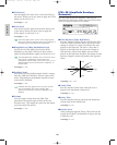
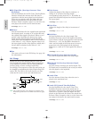
■ Freq K.Flw (Frequency KeyFollow)
Sets the KeyFollow for the Freq (frequency). The
Frequency KeyFollow function controls the change
in the cutoff frequency by the notes played on the
keyboard. When set to a positive value, the higher
the note played on the keyboard, the higher the
cutoff frequency becomes. When a negative value is
set, the lower the note played, the higher the cutoff
frequency becomes. When set to “+32,” the
KeyFollow functions at 100% and the cutoff
frequency changes in proportion to the pitch.
❏ Settings: –32~0~+64
■ Resonance
Sets the resonance quality of an electromagnetic
pickup. This setting determines the amount of
resonance boost near the cutoff frequency set in
Freq.
❏ Settings: 0~31
■ Pan
Sets the panning for the selected FDSP type. This
function determines the left or right positioning of
each FDSP in the stereo spectrum.
❏ Settings: L63 (far left)~cnt (center)~R63 (far right)
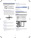
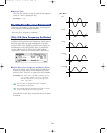
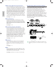
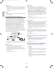
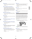
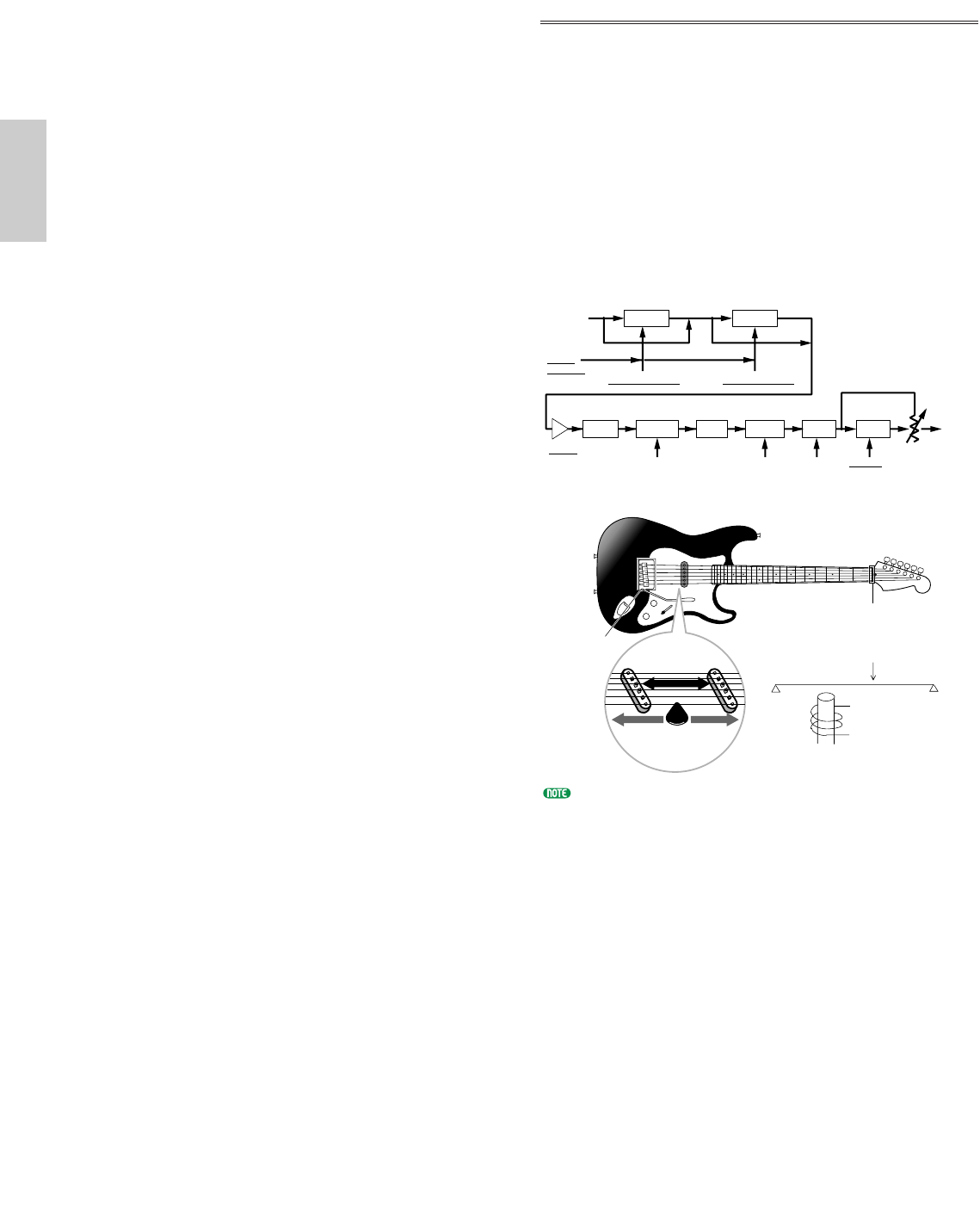
02: EG Pickup (Electric Guitar Pickup)
EG Pickup simulates the electromagnetic pickup of an
electric guitar: tonal changes due to the picking
position and the pickup position, and the
characteristics of an electromagnetic pickup. The
mechanism how the EG Pickup type is formed is as
follows: first, the signal sent to the FDSP unit is
converted into the string vibration. Next, the vibration
is detected by the pickup. Then the signal detected by
the pickup is modified with the frequency
characteristics unique to the electromagnetic pickup,
and output. This system incorporates Yamaha’s Virtual
Acoustic technology.
The underlined items in the diagram are available as the
Destination parameters for the FDSP Controller set (page
141).
Pickup position
Picking position
Nut
Bridge
Pickup
Picking
note dependent note dependent
Delay Delay
Integ
Magnetic Field
Distance
Diff
LPF
Cutoff/
Resonance
Output
Input
Picking position Pickup Position
HPF
Highpass
Filter
bypass
Emp
Pickup type
Flet
control
picking notch
pickup
notch
Drive
Voice/E.qx 5/21/98 11:31 AM Page 126