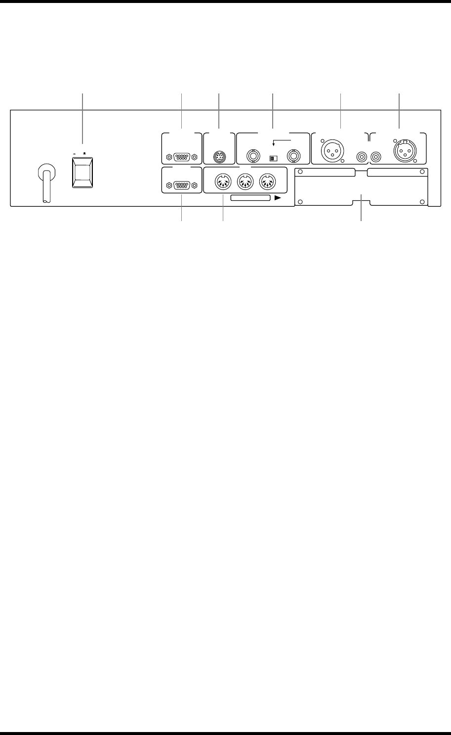
Rear Panel 19
03D—Owner’s Manual
Rear Panel—Lower Half
The lower half of the rear panel consists of digital and control I/O.
A POWER switch
This switch is used to turn on and off the 03D. It’s recessed to prevent accidental oper-
ation.
B TO EDITOR
This 9-pin D-sub connector is used to connect the 03D to video-edit controllers. With
the current version of the 03D system software, however, this function is not yet avail-
able.
C TO HOST
This 8-pin mini DIN connector is used to connect the 03D to a personal computer for
use with MIDI software. It eliminates the need for a separate MIDI interface, and
together with the MIDI standard connections allows the 03D to be used as a MIDI
interface for other MIDI equipment.
D WORD CLOCK
These BNC connectors are used to input and output the system’s wordclock. The 75Ω
wordclock termination switch allows the 03D to be used with various wordclock wiring
schemes. See Wordclock Setup on page 216.
E DIGITAL STEREO OUT
These two connectors are digital stereo outputs. They output the same digital audio sig-
nal but in different formats. The XLR-3-32-type connector outputs AES/EBU format
digital audio (24 bit), while the COAXIAL connector outputs Consumer format digital
audio (20 bit).
F DIGITAL STEREO IN
These two connectors are digital stereo inputs, and only one connection can be used at
a time. The XLR-3-31-type connector accepts AES/EBU format digital audio, while the
COAXIAL connector accepts Consumer format digital audio. Signals input here can be
fed to the stereo input channel or directly to the Stereo bus for stereo cascade operation.
G MOUSE
An optional PC-compatible serial mouse can be connected here for quick navigation
and parameter editing.
3
12 2
3
1
POWER
ON/ OFF
TO EDITOR
TO HOST WORD CLOCK DIGITAL STEREO OUT DIGITAL STEREO IN
MOUSE MIDI
COAXIAL
AES/EBUAES/EBU
IN
OUT
IN
OUT
THRU
75Ω
ON OFF
YGDAI SLOT
8CH INPUTS(CH17-24)/8CH OUTPUTS
1 2
7 8 9
3 4 5 6


