


69
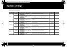
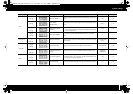
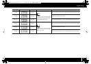
System settings
MIDI
[B1 (8)] MIDI I/F SWITCH
Specifies whether the MIDI connectors will be used as a MIDI inter-
face.
ON p. 76
[B2 (9)]
MIDI MERGE
DESTINATION
Specifies the port that will be merged when the “MIDI MERGE” switch
is On.
PORT 1 p. 77
[A2 (1)]
+
[A1 (0)]
ADVANCED DRIVER
SWITCH
Switches the driver operation mode.
* If you change this setting, the change will take effect the next time
you turn on the power.
ON
p. 78
[A2 (1)]
+
[A2 (1)]
USB UNIT NUMBER
This setting is for future expanded functionality. It is not currently
used.
0 —
Control map
[A2 (1)]
+
[A3 (2)]
STARTUP MEMORY
Specifies which control map will be loaded at startup when the PCR
is powered up.
CONTROL MAP
No. 0
p. 79
Controller
[A2 (1)]
+
[A5 (4)]
VALUE ENCODER Specifies the parameter that the VALUE knob will transmit. KEY VELOCITY p. 80
[A2 (1)]
+
[A6 (5)]
DYNAMIC MAPPING/
V-LINK
Specifies the function of the DYNAMIC MAPPING/V-LINK switch.
DYNAMIC
MAPPING 0
p. 81
Other
[A2 (1)]
+
[A4 (3)]
H-ACTIVITY ON/OFF
Turn this on if you’re using the PCR with certain applications (such as
Pro Tools LE). If this is On, “90 00 7F” will be transmitted from “PCR
2” at intervals of approximately 500 ms.
OFF p. 81
[A2 (1)]
+
[A7 (6)]
FACTORY RESET Returns the PCR-300/500/800’s settings to the factory-set condition. — p. 81
Category
Controller Display Item Contents Factory setting Procedure
PCR-300_500_800_e.book 69 ページ 2006年12月19日 火曜日 午後2時59分