


Chapter 1. Introduction to 3Com VCX IP Telecommuting Module
• Select an IP address for the Telecommuting Module on your network.
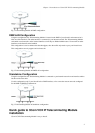
• The network interfaces are marked with 1 and 2. These numbers correspond to the physical interfaces eth0 and
eth1 respectively, the latter which should be use in the installation program.
• Plug in the power cord and turn on the Telecommuting Module.
• Wait while the Telecommuting Module boots up.
• Connect the network cables to the network interfaces.
• Find out the MAC address of the Telecommuting Module’s Network Interface 1 (printed on the Telecommuting
Module label).
• Add a static entry in your local ARP table consisting of the Telecommuting Module’s MAC address and the IP
address it should have on Network Interface 1.
This is how to add a static ARP entry if you use a Windows computer:
Run the command command (or cmd).
In the Command window, enter the command arp -s ipaddress macaddress where ipaddress is the new IP
address for Network Interface 1, and macaddress is the MAC address printed on the Telecommuting Module, but
with all colons (:) replaced with dashes (-).
• Ping this IP address to give the Telecommuting Module its new IP address. You should receive a ping reply if the
address distribution was successful.
• Direct your web browser to the IP address of the Telecommuting Module. You will be prompted to set a
password for the Telecommuting Module admin user.
• Now you can see the top page of 3Com VCX IP Telecommuting Module. Click on the Telecommuting Module
Type link and select the configuration for your Telecommuting Module. The types are described on the web page.
• Go to the Network Interface 1 page and enter the necessary configuration. See also the Interface section. Note
that the Telecommuting Module must have at least one IP address which can be reached from the Internet.
• If one of the Telecommuting Module Types DMZ/LAN or Standalone was chosen, move on to the Network
Interface 2 page and give the Telecommuting Module at least one IP address on this interface and state the
networks connected to the interface. See also the Interface section.
• Go to the Networks and Computers page. Define the networks that will send and receive SIP traffic using the
Telecommuting Module. Usually, you need at least one network per interface of the firewall connected to the
Telecommuting Module (or, for the Standalone type, per interface of the Telecommuting Module). Some
computers should be handled separately, and they therefore need their own networks. See also the Networks and
Computers section.
• Go to the Basic Configuration page under Basic Configuration and enter a Default gateway and a DNS
server. See also the Basic Configuration section.
• Go to the Access Control page and make settings for the configuration of the Telecommuting Module. See also
the Access Control section.
• Go to the Surroundings page (for the DMZ Telecommuting Module Type) and state the networks connected to
the firewall. See also the Surroundings section in chapter 7, Network Configuration.
• Go to Basic under SIP Services and turn the SIP module on. See also the Basic section.
• Go to the Interoperability page. Turn Preserve username and SIP URL encryption on.
• If you use a dialing domain which looks like an IP address, enter the dialing domain in the Translation
exceptions table. See also the Interoperability section.
• For this type of dialing domain, you also need to go to the Routing page. Enter the dialing domain in the DNS
Override For SIP Requests table and state the IP address of the SIP server(s) to handle the domain. See also the
Routing section.
• Go to the Save/Load Configuration page under. Select Apply configuration. Now you can test your new
configuration and save it permanently if you are satisfied with it. If the configuration is not satisfactory, select
Revert or restart the Telecommuting Module. The old configuration will remain.
3