


Edition 3
Rev G
10-2
Section 10
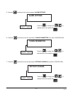
10.1 RELAY TEST
Allows the operator to verify that the LEDs, Relay and/or SSRD output(s) is/are working. A Volt/Ohm meter will be
required to test the output.
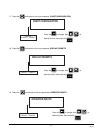
Step 1
With RELAY in the lower display line, depress the and INITIATE RELAY TEST appears in the upper
display line and NO appears in the lower display line. Depress , select YES, depress to perform
the test.
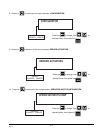
Step 2
TEST IN PROCESS appears in the upper display line, LED 1 will be lit and Relay 1 will be energized or SSRD 1
will be on. For SPDT relays, connect the meter across the NO. and COM output terminals in the ohm scale. The
meter should read continuity with the relay on and infinitity when the relay is off. For SSRD outputs, connect the
meter across the output terminals in the Volt DC scale. The meter should read +5 VDC when the SSRD is on and
0 VDC when the SSRD is off.
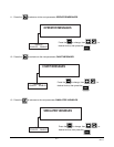
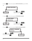
Step 3
When each depression of the advances through each available Relay and/or SSRD. All eight LEDs
should light, one after the other, as all 8 are always present.
Step 4
To exit the test, depress the .
10.2 DISPLAY TEST
Allows the operator to verify that all dots in the VFD are working. No test equipment is required to perform this
test.
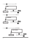
Step 1
With DISPLAY in the lower dipslay line, depress the and INIT DISPLAY TEST appears in the upper display
line and NO appears in the lower display line. Depress , select YES, then depress to perform the
test.
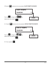
Step 2
All dots in the vacuum fluorescent display will light. With each successive depression of the , the display will
show 2 lines of characters, then all dots being lit, then characters, etc..
Step 3
To exit the test, depress when the lines of characters are displayed. The instrument will return to the
normal display.