


Section 2
2-6
Edition 3
Rev G
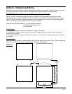
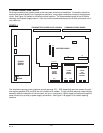
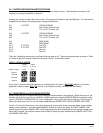
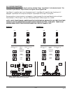
2.3 WIRING CONNECTIONS - INPUTS
All wiring connections are typically made to the instrument at the time of installation. Connections should be
made at the terminal blocks, one 14 gauge wire maximum, using copper conductors except for thermocouple
inputs. See Figure 2-4 (below) for the terminal block locations. The recommended torque for the AC Mains
connector on the power supply board is 113oz-ins and the recommended torque for all other connectors in the
unit is 85oz-ins.
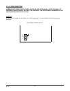
FIGURE 2-4
The instrument case may have numerous conduit openings, EC1 - EC6, depending upon the number of inputs
and outputs specified (EC5 and EC6 are not included on all models). To help minimize electrical noise that may
adversely affect the operation of the instrument, do not run input and/or 4-20mA output connections through the
same conduit entry as relay or power supply connections. See Figure 2-1B (page 2-2) for conduit opening
locations.
2 HIGH
RELAY
BOARD
4 HIGH
INPUT
BOARD
2 HIGH
4-20
OUTPUT
BOARD
TB1
TB1 TB2
J5
J6
Conn J7
J3
J4
J1
POWER
SUPPLY
BOARD
TRANSMITTER POWER SUPPLY BOARD
COMMUNICATIONS BOARD
MOTHER BOARD
AC
MAINS