


Edition 3
Rev G
11-4
Section 11
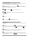
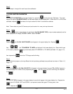
When installing an Input Board for any reason, check the location (where this board is mounted), then verify the
position of JU13 and/or JU14. TC WIDE or TC NARROW were selected, go to Step 5, if not, go to Step 6.
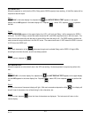
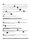
Step 5
Depress the and the upper display line will show IVx CAL CJC OR TC and the lower display line will show
TC, or CJC. Select TC by depressing the , then the until TC is blinking, then depress the
.
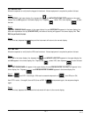
Step 6
Depress the and the upper display line will show IVx PERFORM CAL and the lower display line will show
NO. Select YES to perform the calibration. Connect the appropriate one of the following inputs to the input
terminals of the input being calibrated:
100 ohm resistor RTD Inputs
0.0 mA DC Current Inputs
0.0 mV DC TC or mV DC Inputs
0.0 V DC Volt Inputs
Wait one minute, then depress the key.
Step 7
Connect the appropriate one of the following inputs to the input terminals of the input being calibrated:
277 ohm resistor RTD Inputs
20.00 mA DC Current Inputs
25.00 mV DC TC or 0/25 mV DC Inputs
100.00 mV DC TC or 0/25+ mV DC Inputs
1.00 V DC 1 V DC Inputs
10.00 V DC 10 V DC Inputs
Wait one minute, then depress the key.
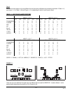
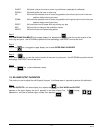
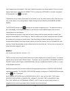
1, 3, 5, 7
JU13
2, 4, 6, 8
JU14
FOR INPUTS
BOARD POSITION
1
2
3
4
Board 4
Board 3
Board 2
Board 1
SIDE
VIEW