


Edition 3
Rev G
Appendix D
D-1
Appendix D - Examples
EXAMPLE 1
Application:
Palmer-Bowlus Flume Height/Flow
Given: Transmitter output linear in distance (4mA=0.0", 20mA=2.85")
Configuration:
Inputs: As required
Custom Curves: See below
Derived Variables: See below
Process Variables (if alarming required): As required
Recorders: See below
Totalizers (if Totals required): As required
Instrument Settings: As required
LEDs/Relays: As required
Chart: As required
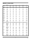
Custom Curves:
Custom Curves Number 1
CC1 Decimal Position of Input 2
CC1 Decimal Position of Output 2
CC1 Number of Points 20
CC1 Point Pair 1 0.00 --> 0.00
CC1 Point Pair 2 0.15 --> 0.30
CC1 Point Pair 3 0.30 --> 1.00
l
l
CC1 Point Pair 20 2.85 --> 50.20
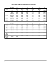
Derived Variables:
DV Number 1
DV1 Display Tag GPM
DV1 Function Custom Curve 1
DV1 Input IV1 (Input configured)
DV1 Display Units Other
DV1 Units Description CPM
DV1 Decimal Position 2
Recorders:
Recorder Number 1
R1 Recorder Tag Flow
R1 Recording Method Drag - Min to Max
R1 Value to Record DV1
R1 Decimal Position 2
R1 Chart Divisions 100
R1 Zone 1 Low Division 0
R1 Zone 1 High Division 100
R1 Span 1 Low 0.00 GPM
R1 Span 1 High 50.20 GPM
R1 Scale Interval 10 Divisions